
Page 146 - Bürkert
P. 146
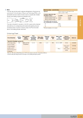
Note                                                 Electrical data - coil AC10 Ex i
           The units may only be used in explosive atmospheres in the manner ap-  Approval  II 2G Ex ia IIC T6 PTB 01 ATEX 2101
           proved by the Federal Institute of Physics and Technology (PTB), i.e., the   II 2D Ex ia D21 T 80°C
           permissible maximum electrical values must be complied with. Suitable   Functional values for valve
                                                                switching function 1)  at +20°C    at +55°C
           barriers and isolating modules are available for this.     Minimum switching current  29 mA  29 mA
                                                                  Nominal resistance of the coil  310 Ω  360 Ω
                        Barrier/                                  Minimum terminal voltage  9.0 V  10.4 V
              PLC       isolating
                        component                               Permissible maximum values
                                                                acc. to certificate of conformity                    6519 Ex i
           The valve is intended for operation on 24 VDC outputs via the intermedi-    Ui  35 V
                                                                  Ii
                                                                                     0.9 A
           ate switching of a corresponding intrinsically-safe operating resource     Pi  1.1 W
           (isolating module or barrier). If required, request the “Recommended   1)  With high impedance coil on request
           Barrier and Isolating Module” data sheet.

           Ordering Chart

                                               Port
                                 Seal material                   Pressure         Body mate-  Pilot air
                          Orifice            connection   QNn-value        Mass
            Circuit function        (Body                         range              rial   thread insert   Item no.
                                                                      2)
                            [mm]              threaded   air  [l/min]        [g]
                                                         1)
                                   material)                       [bar]          pilot valve  material
                                             port [inch]
            Type 6519 threaded version Ex i
            H 5/2-way valve,   8.0  NBR and PUR   G 1/4  1300      2 - 8    670   St. St. 1.4305  St. St.  144 484
            servo-assisted,        (Polyamide)
                                                                                             brass, nickel   144 485
            in de-energized
                                                                                               plated
            position port 2
                                                                                    Brass    brass, nickel   147 252
            pressurized, port 4                                                                plated
            exhausted
           1)  Flow rate:  QNn value air [l/min]: Measured at +20 °C, 6 bar pressure at valve inlet, 1 bar pressure difference
           2)  Pressure values [bar]: Gauge pressures with respect to the prevailing atmospheric pressure


                                                                                                                 145