
Page 176 - Bürkert
P. 176
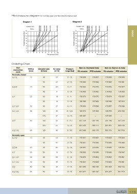
Pilot pressure diagram for normally open and flow direction below seat

                     Diagram 1                                  Diagram 2

                        Actuator size  DN25/                  Ø63  Actuator size  DN15/                  Ø80
                           Orifice   DN15/ Ø40  DN32/ Ø63  DN20/ Ø40  DN40/ Ø63  DN50/ Ø63  Orifice  DN32/ Ø50  DN20/Ø50  DN40/Ø80  DN25/Ø50  DN50/Ø80  DN65/Ø80
                       16                                         16                                                 2000
                      Operating pressure [bar]  12 8 6            Operating pressure [bar]  12 8 6
                       14
                                                                  14
                       10
                                                                  10


                        2 4                                        4 2
                        0                                          0
                         0   1   2   3   4   5   6   7   8   9   10  0   1   2   3   4   5   6   7   8   9   10
                                          Pilot pressure [bar]                       Pilot pressure [bar]


           Ordering Chart
               Port                                                   Item no. Gunmetal body  Item no. Cast st. st. body
             connection   Orifice   Actuator size   Kv value   Pressure
                                                  3
               [inch]     [mm]       Ø [mm]     [m /h]    range [bar]  PA actuator  PPS actuator  PA actuator  PPS actuator
            Normally closed
            G 1/2          13         40         3.7        0 - 15    178 608    178 607    178 606     178 605

                                      50         4.2        0 - 16    178 684    178 683    178 682     178 681

            G 3/4          20         50         8.5        0 - 11    178 680    178 679    178 678     178 677
                                      63          9         0 - 16    178 666    178 665    178 664     178 663

            G 1            25         63          18        0 - 11    178 676    178 675    178 674     178 667
                                      80          18        0 - 16    186 489    187 565    186 488     187 844

            G 1 1/4        32         80          27        0 - 14    178 699    178 698    178 697     178 696

            G 1 1/2        40         100         42       0 - 12.5   185 072    187 829    185 073     235 380
                                      125         42        0 - 16    186 487       –       187 840       –

            G 2            50         100         55       0  - 7.2   001 134    002 170    001 140     001 239

                                      125         55        0 - 10    001 593    002 171    001 601     002 162
            G 2 1/2        65         125         90        0 - 5.2   001 368    002 172    001 373     001 703

            Normally open
            G 1/2          13         40         3.8        0 - 16    178 601    178 602    178 603     178 604

                                      50         4.2        0 - 16    178 691    178 690    178 689     178 688

            G 3/4          20         50         8.5        0 - 16    178 687    179 020    178 686     178 685
            G 1            25         50          10        0 - 16    178 850    178 849    178 848     178 847

            G 1 1/4        32         63          25        0 - 16    178 845    178 853    178 852     178 851
            G 1 1/2        40         63          35        0 - 16    178 864    178 863    178 862     178 861

            G 2            50         80          49        0 - 16    001 595    002 180    001 603     002 164

            G 2 1/2        65         80          77        0 - 16    001 372    002 181    001 377     001 710


                                                                                                                 175