
Page 203 - Bürkert
P. 203
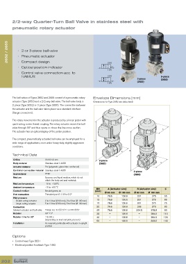
2/2-way Quarter-Turn Ball Valve in stainless steel with
         pneumatic rotary actuator


      2652 / 2655  •  2 or 3-piece ball valve


            •  Pneumatic actuator
            •  Compact design
            •  Optical position indicator                             2 (A)
                                                                      1 (P)
            •   Control valve connection acc. to
               NAMUR                                                  2 (A)                             3-piece
                                                                                         2-piece        (2655)
                                                                                         (2652)
                                                                      1 (P)


         The ball valves of Types 2652 and 2655 consist of a pneumatic rotary   Envelope Dimensions [mm]
         actuator (Type 2050) and a 2/2-way ball valve. The ball valve body is   (Dimensions for Type 2652 see data sheet)
         2-piece (Type 2652) or 3-piece (Type 2655). The connection between
         the actuator and the ball valve takes place via a standard interface
         (flange connection).

         The rotary movement in the actuator is produced by a linear piston with   A
         quick-acting screw thread coupling. The rotary actuator moves the ball
         valve through 90° and thus opens or closes the line cross-section.
                                                                                                         A
         The actuator has an optical display of the piston position.

         The compact, pneumatically actuated ball valve can be employed for a
                                                             B
         wide range of applications, even under heavy-duty, slightly aggressive
         conditions.
                                                                                    B
                                                                               C
         Technical Data
          Orifice             DN10-50 mm                        2-piece
          Body material       Stainless steel 1.4408            (2652)                                  C
          Actuator material   PA (polyamide, glass-fibre reinforced)
          Control air connection material Stainless steel 1.4305                       3-piece
          Seal material       PTFE                                                     (2655)
          Medium              Gaseous and liquid medium, which do not
                                attack the body and seal materials
          Medium temperature  -10 to +120°C
          Ambient temperature  -10 to +60 °C                   DN     A (Actuator size)  B (Actuator size)  C
          Control medium      Neutral gases; air              [mm]  Ø 63 mm  Ø 100 mm  Ø 63 mm  Ø 100 mm
          Port connection     Threaded port G 1/4” to G 2”
                                                               10     79.6     126.6     201      275     65
          Pilot pressure
            Double acting actuator  2 to 10 bar (Ø 63 mm), 2 to 6 bar (Ø 100 mm)  12  79.6  126.6  201  275  65
            Single acting actuator  5 to 10 bar (Ø 63 mm), 5 to 6 bar (Ø 100 mm)  15  79.6  126.6  201  275  75
          Connection                                           20     79.6     126.6     205      279     80
          between actuator and ball valve  Flange acc. to ISO 5211 or DIN 3337  25  79.6  126.6  204.5  278.5  90
          Rotation            90° ±3°                          32      –       126.6      –       284.5   110
          Rotation time for 90°  1 to 3.5 s                    40      –       126.6      –       294.5   120
                              (depending on load and pilot pressure)  50  –    126.6      –       303.5   140
          Installation        As required, preferably with actuator in upright
                              position


         Options
         •  Control head Type 8631
         •  Electrical position feedback Type 1062


  202