
Page 201 - Bürkert
P. 201
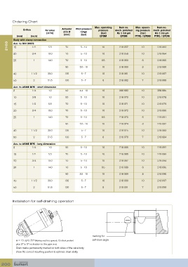
Ordering Chart
                                                             Max. operating   Item no.   Max. operat-  Item no.
                Orifice       Kv value   Actuator   Pilot pressure   pressure   mech. polished   ing pressure   mech. polished
                               [m /h]    size Ø     range         [bar]    Ra ≤ 0.6 µm     [bar]   Ra ≤ 0.6 µm
                                3
            [mm]     [inch]               [mm]      [bar]       EPDM         EPDM      PTFE / EPDM  PTFE / EPDM
          Body with clamp connection
      2103  Acc. to DIN 32676   5.5        70       5 - 10        10         218 057       10        218 063
          15
                     1/2
          20         3/4       10.0        70       5 - 10        10         218 058       10        218 064
          25          1        14.0        70       5 - 10       6.5         218 059       6         218 065

                                           90       5.5 - 10      10         218 060       8         218 066
          40         1 1/2     30.0       130        5 - 7        10         218 061       10        218 067

          50          2        51.5       130        5 - 7        8          218 062       7         218 068

          Acc. to ASME BPE - short dimension
          8          1/4        1.0        50       4.4 - 10      10         266 683       10        266 685

          10         3/8        1.0        50       5 - 10        10         218 070       10        218 078
          15         1/2        5.5        70       5 - 10        10         218 071       10        218 079

          20         3/4       10.0        70       5 - 10        10         218 072       10        218 080

          25          1        14.0        70       5 - 10       6.5         218 073       6         218 081
                                           90       5.5 - 10      10         218 074       8         218 082

          40         1 1/2     30.0       130        5 - 7        10         218 075       10        218 083

          50          2        51.5       130        5 - 7        8          218 076       7         218 084
          Acc. to ASME BPE - long dimension
          8          1/4        1.0        50       5 - 10        10         218 085       10        218 092
          15         1/2        5.5        70       5 - 10        10         218 086       10        218 093

          20         3/4       10.0        70       5 - 10        10         218 087       10        218 094
          25          1        14.0        70       5 - 10       6.5         218 088       6         218 095

                                           90       5.5 - 10      10         218 089       8         218 096

          40         1 1/2     30.0       130        5 - 7        10         218 090       10        218 097
          50          2        51.5       130        5 - 7        8          218 091       7         218 098


         Installation for self-draining operation


                                        α


                                                            marking for
           α = 15 up to 35º (Marking must face upwards, 12 o’clock position)   self-drain angle
           plus 3º to 5º inclination to the pipe axis.
           Drain marks permanently marked on both sides of the valve body
           show the correct mounting position to optimise drain ability.


  200