
Page 369 - Bürkert
P. 369
Ultrasonic Level Transmitter for General Application
8177 G thread process connection
• Two-wire version
• Reliable non-contact measurement
• HART configuration
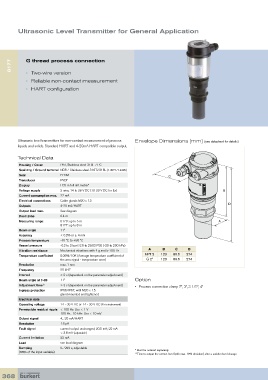
Ultrasonic level transmitters for non-contact measurement of process Envelope Dimensions [mm] (see datasheet for details)
liquids and solids. Standard HART and 4-20mA HART compatible output.
Technical Data
Housing / Cover PBT, Stainless steel 316L / PC
Seal ring / Ground terminal NBR / Stainless steel 316Ti/316L (1.4571/1.4435)
Seal EPDM C
Transducer PVDF
Display LCD in full dot matrix*
Voltage supply 2-wire, 14 to 36 V DC (10-30 V DC for Ex) B
Current consumption max. 22 mA
Electrical connections Cable glands M20 x 1.5
D
Outputs 4-20 mA/HART
Output load max. See diagram
Dead zone 0.4 m
Measuring range: 8176: up to 5 m A
8177: up to 8 m
Beam angle 11°
Accuracy < 0.2% or ± 4 mm
Process temperature -40 ºC to +80 ºC
Vessel pressure -0.2 to 2 bar (-2.9 to 29.02 PSI) (-20 to 200 kPa)
Vibration resistance Mechanical vibrations with 4 g and 5-100 Hz A B C D
Temperature coefficient 0.06%/10K (Average temperature coefficient of NPT 2 123 80.5 274
the zero signal - temperature error) G 2" 123 80.5 274
Resolution max. 1 mm
Frequency 55 kHZ
Interval > 2 s (dependent on the parameter adjustment)
Beam angle at 3 dB 11° Option
Adjustment time 1) > 3 s (dependent on the parameter adjustment) • Process connection clamp 2”, 3”, 3 1/2”, 4”
Ingress protection IP66/IP67, with M20 x 1.5
gland mounted and tightened
Electrical data
Operating voltage 14 - 36 V DC or 14 - 30 V DC (Ex ia instrument)
Permissible residual ripple < 100 Hz: Uss < 1 V
100 Hz... 10 kHz: Uss < 10 mV
Output signal 4... 20 mA/HART
Resolution 1.6 µA
Fault signal current output unchanged; 20.5 mA; 22 mA
< 3.6 mA (adjustable)
Current limitation 22 mA
Load see load diagram
Damping 0... 999 s, adjustable
(63% of the input variable) * Must be ordered separately
1) Time to output the correct level (with max. 10% deviation) after a sudden level change.
368