
Page 226 - Bürkert
P. 226
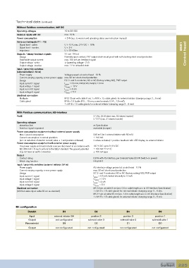
Technical data (continued)
            Without fieldbus communication; 24V DC
            Operating voltages            12 to 28 VDC
            Residual ripple with DC       max. 10 %
            Power consumption             < 5 W (acc. to version and operating status see instruction manual)
            Valve control inputs (Y1 - Y3)
              Signal level - active       U > 10 V, max. 24 V DC + 10%                                              8681
              Signal level - inactive     U < 5 V
              Impedance                   U > 30 kOhm
            Outputs / binary feedback signals  S1 out - S4 out                                                        Control head
              Design                      Normally open contact, PNP output short-circuit proof with self-clocking short circuit protection
              Switchable output current   max. 100 mA per feedback signal
              Output voltage -active      ≥ (operating voltage - 2 V)
              Output voltage -inactive    max. 1 V in unloaded state
            Input / proximity switches
            (external initiator: S4 in)
              Power supply                Voltage present at control head - 10 %
               Current carrying capacity, sensor power supply  max. 90 mA short-circuit protection
              Design                      DC 2- and 3-conductor, NO or NC (factory setting NO), PNP output
              Input current 1 signal      I   > 6.5 mA, limited internally to 10 mA
                                          Sensor
              Input voltage 1 signal      U   > 10 V
                                           Sensor
              Input current 0 signal      I   < 4 mA
                                          Sensor
              Input voltage 0 signal      U   < 5 V
                                           Sensor
            Electrical connection
              Multipole                   M12 12-pin with cable 8 cm, 1 x M16 x 1.5 cable glands for external initiator (clamping range 3 ... 6 mm)
                                                                              2
              Cable gland                 M16 x 1.5 (cable-Ø 5 ... 10 mm, screw terminals 0.14 ... 1.5 mm ),
                                          1 x M16 x 1.5 cable glands for external initiator (clamping range 3 ... 6 mm)
            With Fieldbus communication; AS-Interface
            Profil                                          S-7.A.E (A/B slave max. 62 slaves/master)
                                                            S-7.F.F (max. 31 slaves/master)
            Operating voltages
              above bus line                                as Specification
              from bus signal separated                     reversible (Jumper)
            Power consumption equipment without external power supply
              Max. Current consumption                      240 mA (incl. external initiator with 90 mA)
               Current consumption in normal operation      ≤ 150 mA
             (acc. to reduction of electric current; valve + 1 end position achieved)  3 valves activated, 1 position feedback with LED display, no external initiator
            Power consumption equipment with external power supply
               The power supply unit must include a secure disconnect in accordance with   19.2 V DC up to 31.6 V DC
             IEC 364-4-41. It must conform to the SELV standard. The ground potential   ≤ 100 mA 24 V DC
             may not have an earth connection.              ≤ 150 mA type.
            Output
              Contact rating                                0.8 W with AS-Interface, per Solenoid Valve (0.9 W Switch-on power)
              Watch-dog function                            integrated
            Input / proximity switches (external Initiator: S4 in)
              Power supply                                  AS interface voltage present at control head - 10 %
              Current carrying capacity, sensor power supply   max. 30 mA short-circuit protection
              Design                                        DC 2- and 3-conductor, NO or NC (factory setting NO), PNP output
              Input current 1 signal                        I   > 6.5 mA, limited internally to 10 mA
                                                            Sensor
              Input voltage 1 signal                        U   > 10 V
                                                             Sensor
              Input current 0 signal                        I   < 4 mA
                                                            Sensor
              Input voltage 0 signal                        U   < 5 V
                                                             Sensor
            Electrical connection                           M12 4-pin at cable 8 cm (acc. 0.3 m cable length acc. to AS-Interface Specification)
            (ASI flat cable clip at cable 80 cm as standard)  1 x M 16 x 1.5 cable glands for external initiator clamping range 3 ... 6 mm.
                                                            M12 4-pin at cable 80 cm (acc. 1.0 m cable length acc. to AS-Interface Specification)
                                                            1 x M 16 x 1.5 cable glands for external initiator clamping range 3 ... 6 mm.
           Bit configuration
                   Databit              D3                   D2                  D1                  D0
                    Input          external initiator S4  position 3           position 2          position 1
                   Output           not configurated     solenoid valve 3    solenoid valve 2    solenoid valve 1
                 Parameterbit           D3                   D2                  D1                  D0
                   Output           not configurated    not configurated     not configurated    not configurated


                                                                                                                 225