
Page 231 - Bürkert
P. 231
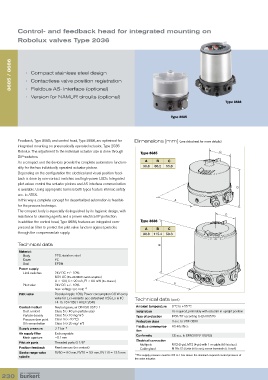
Control- and feedback head for  integrated mounting on
           Robolux valves Type 2036


      8685 / 8686  •  Compact stainless steel design


            •  Contactless valve position registration
            •  Fieldbus AS- Interface (optional)
            •   Version for NAMUR circuits (optional)
                                                                                                     Type 8686


                                                                             Type 8685


         Feedback, Type 8685, and control head, Type 8686, are optimised for   Dimensions [mm] (see datasheet for more details)
         integrated mounting on pneumatically operated actuator, Type 2036
         Robolux. The adjustment to the individual actuator size is done through   Type 8685      C
         DIP-switches.
         As a compact unit the devices provide the complete automation function-  A  B  C
         ality for the two individually operated actuator pistons.  90.8  86.2  55.8
         Depending on the configuration the electrical and visual position feed-
         back is done by non-contact switches and high-power LEDs. Integrated
         pilot valves control the actuator pistons and AS-interface communication
                                                                                                          B
         is available. Using appropriate barriers both types feature intrinsic safety
         acc. to ATEX.
         In this way a complete concept for decentralized automation is feasible   A
         for the process technique.
         The compact body is especially distinguished by its hygienic design, with
         resistance to cleaning agents and a proven electrical IP protection.                        C
         In addition the control head, Type 8686, features an integrated com-  Type 8686
         pressed air filter to protect the pilot valve function against particles
                                                                 A     B    C
         through the compressed air supply.                      90.8  115.4  50.3

         Technical data                                                B
          Material:
            Body         PPS, stainless steel
            Cover        PC
            Seal         EPDM
          Power supply
            Limit switches  24V DC +/- 10%
                         8.2V DC (Ex-i-NAMUR switch amplifier)
                         U < 12V, Ii < 20 mA, Pi < 60 mW (Ex- Barrier)
            Pilot valve  24V DC +/- 10%                                       A
                         max. voltage see note
                                       2)
          Pilot valve    Residual ripple 10%; Power consumption 0.8 W every
                         valve for Ex i-variants: acc datasheet II 2G Ex ia IIC   Technical data (cont.)
                         T4 T5 T6 PTB01 ATEX 2048
          Control medium  Neutral gases, air DIN ISO 8573-1   Ambient temperature  0 ºC to +55 ºC
            Dust content   Class 5 (<40 µm particle size)     Installation   As required, preferably with actuator in upright position
            Particle density  Class 5 (<10 mg/m ) 3           Type of protection  IP65/67 according to EN 60529
            Pressure dew point  Class 3 (<-20 °C)             Protection class  3 acc. to VDE 0580
            Oil concentration  Class 5 (<25 mg/ m ) 3
          Supply pressure  3-7 bar  1)                        Fieldbus communica-  AS-Interface
                                                              tion
          Air supply filter  Exchangeable                                    CE acc. to EMV2004/108/EG
            Mesh aperture  ~0.1 mm                            Conformity
                                                              Electrical connection
          Pilot air ports  Threaded ports G 1/8”
                                                                Multipole    M12 (8-pin), M12 (4-pin) with 1 m cable (AS-Interface)
          Position feedback  Reed sensors (no contact)          Cable gland  M16x1.5 (Cable Ø 6.5 mm), screw terminals (1.0 mm 2 )
          Stroke range valve   RV50 = 6.0 mm, RV70 = 9.5 mm, RV110 = 13.5 mm  1)  The supply pressure must be 0.5 to 1 bar above the minimum required control pressure of
          spindle
                                                             the valve actuator.

  230