
Page 30 - Bürkert
P. 30
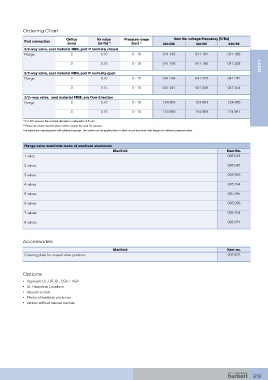
Ordering Chart
                              Orifice       Kv value    Pressure range        Item No. voltage/frequency [V/Hz]
            Port connection
                               [mm]          [m³/h]  1)    [bar]  1)     024/DC         024/50        230/50
            3/2-way valve, seal material NBR, port P normally closed
            Flange              2             0.10          0 - 16       041 183        041 184       041 188
                                                                                                                     0331
                                3             0.15          0 - 10       041 195        041 198       041 209

            3/2-way valve, seal material NBR, port P normally open
            Flange              2             0.10          0 - 16       041 234        041 235       041 242

                                3             0.15          0 - 10       041 247        041 248       041 254
            3/2--way valve,  seal material FKM, any flow direction
            Flange              2             0.10          0 - 16       124 953        124 954       124 956
                                3             0.15          0 - 10       124 958        124 959       124 961

           1)  For DC versions the nominal diameter is reduced to 0.5 mm.
           2)  Please be aware that the above valves cannot be used for vacuum.
           The valves are manufactured with different springs. The valves can be applied also in other circuit functions with respect to different pressure rates.


            Flange valve manifolds made of anodised aluminium
                                                   Manifold                                           Item No.
            1 valve                                                                                   005 043
            2 valves                                                                                  005 045

            3 valves                                                                                  005 366
            4 valves                                                                                  005 294

            5 valves                                                                                  005 295

            6 valves                                                                                  005 296
            7 valves                                                                                  005 403

            8 valves                                                                                  006 074


           Accessories

                                                   Manifold                                           Item no.
            Covering plate for unused valve positions                                                 005 625


           Options
           •  Approvals UL, UR, GL, CGA / AGA
           •  UL Hazardous Locations
           •  Vacuum version
           •  Electrical feedback positioner
           •  Version without manual override


                                                                                                                 29