
Page 306 - Bürkert
P. 306
91
85.5 (21) R90
164.50
203 (30)
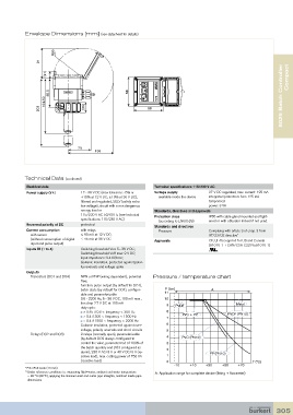
Envelope Dimensions [mm] (see datasheet for details)
R90
70
91 136
8025 Batch Controller
(21) Compact
85.5 88
164.50
203 (30) 88
70
136
Technical Data (continued)
88
Electrical data Technical specifications 115/230 V AC
Power supply (V+) 12 - 36 V DC (max tolerance: -5% or Voltage supply 27 V DC regulated, max. current: 125 mA
88 +10% at 12 V DC; ±10% at 36 V DC), available inside the device integrated protection: fuse 125 mA
filtered and regulated, SELV (safety extra temporised
low voltage), circuit with a non dangerous power: 3 VA
energy level or Standards, directives and approvals
115/230 V AC 50/60 Hz (see technical Protection class IP65 with cable gland mounted and tight-
specifications 115/230 V AC) (according to EN60529) ened or with obturator locked if not used.
Reversed polarity of DC protected
Standards and directives
Current consumption with relays Pressure Complying with article 3 of chap. 3 from
with sensor ≤ 90 mA at 12 V DC; 97/23/CE directive*
(without consumption of digital ≤ 45 mA at 36 V DC Approvals CE; UL-Recognized for US and Canada
input and pulse output) (61010-1 + CAN/CSA-C22 No.61010-1)
Inputs DI (1 to 4) Switching threshold Von: 5... 36 V DC;
Switching threshold Voff max: 2 V DC;
Input impedance: 9.4 KOhms;
Galvanic insulation, protected against polar-
ity reversals and voltage spike
Outputs
Transistors (DO1 and DO4) NPN or PNP (wiring dependent), potential Pressure / temperature chart
free;
function: pulse output (by default for DO1),
batch state (by default for DO4), configur- P (bar) A
able and parameterizable 11
0.6 - 2200 Hz, 5 - 36 V DC, 100 mA max., 10
line drop 2.7 V DC at 100 mA 9 Metal
duty cycle: PVDF
> 0.45 if 0.6 < frequency < 300 Hz 8 PVDF (PN10)
> 0.4 if 300 < frequency < 1500 Hz 7 PVC + PP
< 0.4 if 1500 < frequency < 2200 Hz
Galvanic insulation, protected against over- 6
voltage, polarity reversals and short-circuits 5
Relays (DO2 and DO3) 2 relays (normally open), parameterizable
(by default: DO2 always configured to 4 PVC (PN10)
control the valve, parameterized of 100% of 3
the batch quantity and DO3 configured as 2
alarm), 230 V AC/3 A or 40 V DC/3 A (re- PP (PN10)
sistive load), max. cutting power of 750 VA 1
(resistive load) 0 T (°C)
-10 +10 +30 +50 +70
* F.S.=Full scale (10 m/s)
1) Under reference conditions i.e. measuring fluid=water, ambient and water temperature
A: Application range for complete device (fitting + flowmeter)
= 20 °C (68 °F), applying the minimum inlet and outlet pipe straights, matched inside pipe
dimensions
305