
Page 310 - Bürkert
P. 310
Technical data (continued)
Electrical data Technical specifications 115/230 V AC
Power supply (V+) Supply voltage Wall-mounted version:
Panel- and wall-mounted version 12 - 36 V DC (max tolerance: -5% or available inside the device Voltage supply: 27 V DC regulated,
+10% at 12 V VC; ±10% at 36 V DC), Max. current: 250 mA
filtered and regulated, SELV (safety extra Integrated protection: fuse 250 mA
Wall-mounted version low voltage) circuit with a non dangerous temporised
energy level, Power: 6 VA
115/230 V AC 50/60 Hz (see technical Standards, directives and approvals
specifications 115/230 V AC) Protection class IP65 (panel-mounted and wall-mounted
Reversal polarity of DC Protected (according to EN60529) version) device wired and cable glands
Current consumption (without consumption of current output of tightened screwed tight
with sensor the flowmeter) IP20 (panel-mounted version, inside the 8025 Batch controller
≤ 90 mA (at 12 V DC); ≤ 45 mA (at cabinet)
36 V DC); ≤ 55 mA (115/230 V AC) Approvals CE; UL-Recognized for US and Canada
Controller input (61010-1 + CAN/CSA-C22 No.61010-1)
(from sensor) 0.6 Hz to 2.2 kHz,
Frequency range max. voltage: 36 V DC
Open collector NPN (with 470 Ω or 2.2 kΩ
resistance) or PNP, Coil, TTL, CMOS (with
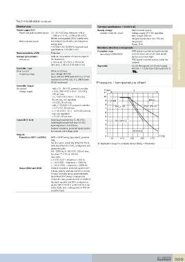
39 kΩ resistance) Pressure / temperature chart
Controller output
(to sensor) - with a 12 - 36 V DC powered controller:
P (bar)
Voltage supply 10.5... 34.5 V DC [=(V+) - 1.5 V DC], 11 A
140 mA max.
0... 23.5 V DC [=(V+) - 12.5 V DC], 10
80 mA max. non regulated 9 PVDF Metal
5 V DC, 30 mA max.
- with a 115/230 V AC powered controller: 8 PVC + PP PVDF (PN10)
+27 V DC, 80 mA max. 7
+14.5 V DC [=(V+) - 12.5 V DC] 80 mA
max. non regulated 6
5 V DC, 30 mA max. 5
Inputs DI (1 to 4) Switching threshold Von: 5... 36 V DC; 4 PVC (PN10)
Switching threshold Voff max: 2 V DC;
Input impedance: 9.4 KOhms; 3
Galvanic insulation, protected against polar- 2
ity reversals and voltage spike 1 PP (PN10)
Outputs
Transistors (DO1 and DO4) NPN or PNP (wiring dependent), potential 0 -10 +10 +30 +50 +70 T (°C)
free;
function: pulse output (by default for DO1), A: Application range for complete device (fitting + flowmeter)
state (by default for DO4), configurable and
parameterizable
0.6 - 2200 Hz, 5 - 36 V DC, 100 mA max.,
line drop 2.7 V DC at 100 mA
duty cycle:
> 0.45 if 0.6 < frequency < 300 Hz
> 0.4 if 300 < frequency < 1500 Hz
< 0.4 if 1500 < frequency < 2200 Hz
Relays (DO2 and DO3) Galvanic insulation, protected against over-
voltage, polarity reversals and short-circuits
2 relays (normally open), parameterizable
(by default: DO2 always configured to
control the valve, parameterized of 100% of
the batch quantity and DO3 configured as
alarm), 230 V AC/3 A or 40 V DC/3 A (re-
sistive load), max. cutting power of 750 VA
(resistive load)
309