
Page 340 - Bürkert
P. 340
Technical Data (continued )
Linearity ±0.5% of F.S. 1) Standards, directives and approvals
Repeatability ±0.25% of Reading 1) Protection class IP65, device wired and cable glands tightened
and lid screwed tight
1) Under reference conditions i.e. measuring fluid=water, ambient and water temperature =
20 °C (68°F), applying the minimum inlet and outlet straight pipe lengths, matched inside Standards and directives
pipe dimensions. EMC EN 61000-6-2, EN 61000-6-3
* F.S.= of Full scale (10 m/s)
Low voltage (LVD) EN 61010-1
Electrical data Pressure Complying with article 3 of §3 from 97/23/ 8045
Operating voltage 18 - 36V DC filtered and regulated (3 wires) Vibration CE directive.*
Tolerance: ±0.5% Shock EN 60068-2-6
Reversed polarity of DC protected Approvals EN 60068-2-27
FDA (only for device with FKM seal and PEEK
Current consumption ≤ 300 mA (at 18V DC) electrode holder)
Digital input DI1 Supply voltage: 18 - 36V DC, KTW (only for device with EPDM seal and
input impedance 15 kΩ PVDF sensor holder)
min. pulse duration: 200 ms Available version with CSA-Approved for US
Galvanic insulation, protected against polarity
and Canada C US , on request
reversals of DC and voltage spikes * For the 97/23/CE pressure directive, the device can only be used under following condi-
Digital outputs tions (dependent on max. pressure, pipe diameter and fluid).
Transistor (DO1) Type: NPN or PNP (wiring dependent), open
collector Type of fluid Conditions
Function: pulse output (by default), user Fluid group 1, §1.3.a Forbidden
configurable
0 - 250 Hz, 5 - 36V DC, 100 mA max., Fluid group 2, §1.3.a DN ≤ 32, or
duty cycle if frequency > 2 Hz: 1/2; min. pulse DN > 32 and PN*DN ≤ 1000
duration if frequency < 2 Hz: 250 ms Fluid group 1, §1.3.b PN*DN ≤ 2000
Relay (DO2 and DO3) Galvanic insulation, protected against polarity Fluid group 2, §1.3.b DN ≤ 200 or
reversals of DC and short-circuits PN ≤ 10 or PN*DN ≤ 5000
2 normally open relays, freely adjustable
(hysteresis by default), 250V AC/3 A or
30V DC/3 A (resistive load), max. cutting
power of 750 VA (resistive load); life span of
min. 100000 cycles
Analogue output
Current (AO1) 4... 20 mA, sink or source (wiring dependent),
22 mA to indicate a fault
max. loop impedance: 1300 Ω at 36V DC,
1000 Ω at 30V DC, 700 Ω at 24V DC, 450 Ω
at 18V DC
4... 20 mA output accuracy ±1%
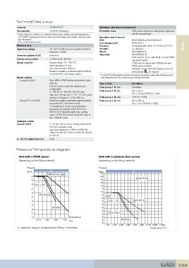
Pressure/Temperature diagram
8045 with a PVDF sensor 8045 with a stainless steel sensor
(depending on the fitting material) (depending on the fitting material)
Pressure Pressure
A
(Bar) (Bar) A
PVDF (PN10) / Metal 16
10 15
9 14 Metal (PN16)
13
8 PVC + PP 12
7 11
6 10
PVC (PN10) 9
5 PVDF
8
4 7 PVC + PP PVDF (PN10)
3 6
PP (PN10) 5
2
4
1 3 PVC (PN10)
0 Temperature 2
+10 +30 +50 +70 1 PP (PN10)
(°C)
0
-10 +10 +30 +50 +70 +90 +110 +130 +150
A : application range for complete device (Fitting + transmitter) Temperature (°C)
339