
Page 362 - Bürkert
P. 362
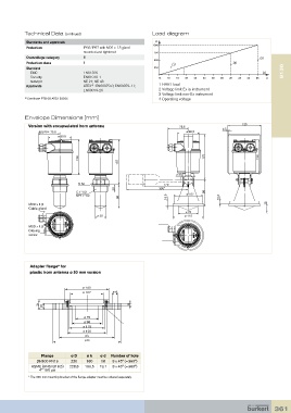
Technical Data (continued)                          Load diagram
            Standards and approvals
                                                                1000
            Protection             IP66/IP67 with M20 x 1.5 gland
                                   mounted and tightened        750
            Overvoltage category   III                                                                      3
                                                                500
            Protection class       II                                   1                        2
            Standard                                            250
               EMC                 EN61326                                                                   4       8136
             Security              EN61010-1                      14  16  18  20  22  24  26  28  30  32  34  36  V
             NAMUR                 NE 21; NE 43
            Approvals              ATEX  : EN60079-0; EN60079-11;   1 HART load
                                      2)
                                   EN60079-26                     2 Voltage limit Ex ia instrument
                                                                  3 Voltage limit non-Ex instrument
           2)  Certificate PTB 08 ATEX 2002X                      4 Operating voltage


           Envelope Dimensions [mm]

             Version with encapsulated horn antenna                         75,5            2,5     125
                 approx.                                                     ø 80,5
                            75.5
                         ø 80.5


                                 123                                                 170                   123
                                                 157

                                                                         ø 40
                                  50                                170
                                                22                300*
                                G 1”1/2                                              98
                                NPT 1”1/2         80                 18,5    ø 107         10,5
             M20 x 1,5                                                                                        15
             Cable gland
                                                                             ø 75
                                         ø 39                                ø 115
             M20 x 1,5
             Closing
             screw


             Adapter flange* for
             plastic horn antenna ø 80 mm version


                                   ø 143
                                   ø 107       ø d

                 31  20                               8

                                   ø 75
                                   ø 98
                                   ø 115
                                   ø 126
                                    ø k
                                    ø D


                  Flange      ø D    ø k  ø d  Number of hole
                DN100 PN16    220   180   18   8 x 45° (=360°)
              ASME (ANSI B16,5)    228,6  190,5  19,1  8 x 45° (=360°)
                 4” 150 psi
             *  The 300 mm mounting bracket of the flange adapter must be ordered separately.


                                                                                                                 361