
Page 395 - Bürkert
P. 395
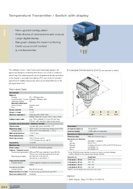
Temperature Transmitter / Switch with display


      8400  •  Menu-guided configuration
            •  Wide choice of connections and outputs

            •  Large digital display
            •  Bar graph display for local monitoring
            •  Continuous on/off control
            •  2-wire transmitter


         This intelligent sensor / switch with a particularly large display is de-  Envelope Dimensions [mm] (see datasheet for details)
         signed specifically for monitoring limit values or an on/off or continuous
         control loop. The switching points can be programmed directly via buttons
         on the display or optionally externally by a PLC via a 4-20 mA standard        B
         signal input. In addition, the process value can be transmitted via a 4-20
         mA signal to the PLC.

         Technical Data
          General data                                                                       C
          Materials
            Housing        PC, +20% glass fibre
            Front panel folio / Screws Polyester / Stainless steel
            Cable plug, Multipin    PA
            Materials wetted parts
            Sensor element      Stainless steel                  D
            Seal           FKM
          Sensor element   Pt100                                     A
          Screw-in thread  G 1/2”                                                   A      B     C      D
          Electrical connections  Cable plug: EN 175301-803                        29.5   54     54    103.5
                           Multipin: swivel M12, 5-pin or M12, 4-pin or 8-pin
                                                   2
          Voltage supply cable  max. 100 m, shielded, 0.14 up to 0.5 mm  max.
                           5 Ω max. cable impedance (Wall-mounted version)
          Complete device data (pipe + electronic module)
          Pipe diameter    Any pipe with sensor connection 1/2”  Environment
          Measuring range  -40 to +125 °C (for ambient temp. between 0 and +40°C)  Ambient temperature  -20 up to 60 °C
            Compact version  -40 to +90 °C (for ambient temp. > +40 °C)  Relative humidity  ≤ 80%, without condensation
          Medium temperature  +125 °C max.                    Standards, directives and approvals
          Fluid pressure max.  PN16                           Protection class  IP65 with connector plug-in
          Switching accuracy  ±0.5 °C (0 up to +80 °C)        Standards and directives
                           ±1.5 °C (outside of 0 up to +80 °C)    EMC           EN 50081-1, 50082-2
          Repeatability    ≤ ±0.4%                              Security        EN 61010-2
          Electrical data                                       Pressure        Complying with article 3 of §3 from 97/23/CE directive.*
          Power supply     12-30V DC , filtered and regulated    Vibration      EN 60068-2-6
                                                                Shock           EN 60068-2-27
          Outputs - Compact version
            Transistor (programmable) NPN and PNP, open collector, 5 up to 30V DC,   *  For the 97/23/CE pressure directive, the device can only be used under following
                           700 mA max., protected against short circuits  conditions (depend on max. pressure, pipe diameter and fluid).

            Relay (programmable)  3A/250V AC or 3A/30V DC
                           3A/48V AC or 3A/30V DC  1)         Type of fluid     Conditions
          Input external setpoint                             Fluid group 1, §1.3.a  DN25 only
            Compact version  4-20 mA, galvanic insulation, max. input impedance:   Fluid group 2, §1.3.a  DN ≤ 50
                           250 Ω                              Fluid group 1, §1.3.b  DN ≤ 50
          Current consumption                                 Fluid group 2, §1.3.b  DN ≤ 50
            Compact version  Max. 80 mA (no load)            1)  Valid for: external setpoint input and process value output
          Response time (10 to 90%)  7 s (for one step increment from 0 up to 100 °C
          Reversed polarity of DC  Protected
                                                             Option
                                                             •  8400: Outputs : Relay 3 A/250 or 3 A/30V DC

  394