
Page 390 - Bürkert
P. 390
Technical Data (continued)
Electrical data Standards, directives and approvals
Power supply 12-30 V DC , filtered and regulated Protection class IP65 with connector plug-in
Overvoltage protection Yes, for power supply and for transistor outputs Standards and directives
Current consumption EMC Transmitter version: EN 50081-1, 61000-6-2
Transmitter 2-wire version < 30 mA (+700 mA max. per transistor output used) Switch version: EN 50081-1 ,50082-2
Switch version < 750 mA (with load - PNP output configuration) Low voltage Transmitter version: EN 61010-1 8311
< 80 mA (with load - Relay version) Switch version: EN 61010-1
Output Pressure Complying with article 3 of §3 from 97/23/CE
directive.*
Transmitter 2-wire version Vibration EN 60068-2-6
Transistor (programmable) open collector, 2 NPN or 2 PNP, 700 mA max., Shock EN 60068-2-27
NPN: [(V+) minus 0.5 VDC] - 0 VDC
PNP: 0.5 VDC - (V+) * For the 97/23/CE pressure directive, the device can only be used under following condi-
protected against short circuit tions (depend on max. pressure, pipe diameter and fluid).
Process value 4-20 mA, Loop resistance: 800 Ω at 30 V DC,
550 Ω at 24 V DC, 300 Ω at 18 V DC Type of fluid Conditions
(For more details, see instruction manual) Fluid group 1, §1.3.a DN25 only
Fluid group 2, §1.3.a DN≤32, or
Switch version open collector, NPN / PNP, 700 mA max., DN>32 and PN*DN ≤1000
Transistor (programmable) NPN: 0.2 - 30 VDC ; PNP: (V+)
protected against short circuit Fluid group 1, §1.3.b DN≤25, or
Optional relay (programmable) Normally open/normally closed DN>25 and PN*DN ≤2000
3 A / 250 V AC or 3 A / 30 V DC (relay) Fluid group 2, §1.3.b DN≤200
Reversed polarity of DC Protected (for power supply and all outputs)
Environment
Ambient temperature 0 up to 60°C (operating and storage)
Relative humidity ≤ 80%, non condensated
Main features
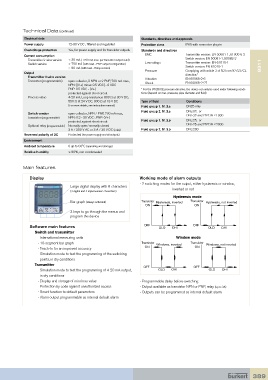
Display Working mode of alarm outputs
Large digital display with 8 characters - 2 switching modes for the output, either hysteresis or window,
(4 digital and 4 alphanumeric characters) inverted or not
Hysteresis mode
Bar graph (always activated) Transistor Transistor
ON Hysteresis, inverted ON Hysteresis, not inverted
3 keys to go through the menus and
program the device
Software main features OFF OLO OHI OFF OLO OHI
Switch and transmitter
- International measuring units Window mode
- 10-segment bar graph Transistor Windows, inverted Transistor Windows, not inverted
- Teach-In for an improved accuracy ON ON
- Simulation mode to test the programming of the switching
points, in dry conditions
Transmitter OFF OFF
- Simulation mode to test the programming of 4-20 mA output, OLO OHI OLO OHI
in dry conditions
- Display and storage of min/max value - Programmable delay before switching
- Protection by code against unauthorized access - Output available as transistor NPN or PNP, relay (up to 3A)
- Reset function to default parameters - Outputs can be programmed as internal default alarm.
- Alarm output programmable as internal default alarm
389