
Page 405 - Bürkert
P. 405
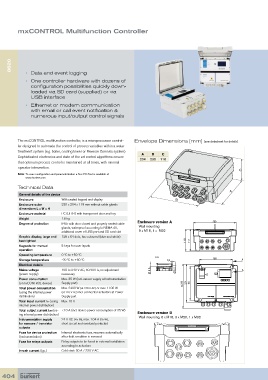
mxCONTROL Multifunction Controller


      8620


            •  Data and event logging
            •   One controller hardware with dozens of
                   configuration possibilities quickly down-
               loaded via SD card (supplied) or via
               USB interface
            •   Ethernet or modem communication
               with email or call event notification &
               numerous input/output control signals


         The mxCONTROL multifunction controller, is a microprocessor control-  Envelope Dimensions [mm] (see datasheet for details)
         ler designed to automate the control of process variables within a water
         treatment system (e.g. boiler, cooling tower or Reverse Osmosis system).
                                                                A   B    C
         Sophisticated electronics and state of the art control algorithms ensure
                                                               204  230  116
         that optimum process control is maintained at all times, with minimal
         operator intervention.
                                                                                                           C
         Note:  To ease configuration and parameterization a free PC-Tool is available at
            www.burkert.com
         Technical Data
                                                                                                       A
          General details of the device
          Enclosure         With sealed keypad and display                     B
          Enclosure outer   230 x 204 x 119 mm without cable glands
            dimensions L x W x H
          Enclosure material  PC (UL94) with transparent door and key
          Weight            1.8 kg
          Degree of protection  IP65 with door closed and properly sealed cable   Enclosure version A  230
                            glands, waterproof according to NEMA 4X,   Wall mounting
                              additional cover of USB port and SD card slot  9 x M16, 1 x  M32
          Graphic display, large and   128 x 64 dots, two coloured (blue and white)
          backlighted                                                              119  116
          Keypads for manual   5 keys for user inputs
            operation
          Operating temperature  0 ºC to +50 ºC                       A-A
          Storage temperature  -20 ºC to +60 ºC                            6,5                  180         A
          Electrical details
          Mains voltage     100 to 240 V AC, 50/60 Hz, no adjustment   Ø 9,5   Ø5,2                          A
          (power supply)    necessary
          Power consumption    Max. 35 W (incl. sensor supply at Instrumentation
          (of mxCONTROL device)  Supply part)                                     236  204  180
          Total power consumption   Max. 2400 W (at 240 V AC) or max. 1100 W      ca.
          (using the internal power   (at 110 V AC) incl. connected actuators at Power
          distribution)     Supply part
          Total input current Iin (using  Max. 10 A
          internal power distribution)
          Total output current Iout (us-  <10 A (incl. device power consumption of 35 W)
          ing internal power distribution)                    Enclosure version B
          Instrumentation supply   24 V DC (±5 %), max. 1.04 A (25 W),   Wall mounting, 6 x M16, 3 x M20, 1 x M32
          for sensors / transistor   short circuit and overload protected
          outputs
          Fuse for device protection   Internal: electronic fuse, recovers automatically
          (Instrumentation)  after fault condition is removed
          Fuse for relays outputs  Relay outputs to be fused in external installation
                            according to actuators
          Inrush current (typ.)  Cold start: 30 A / 230 V AC


  404