
Page 402 - Bürkert
P. 402
Technische Daten (Fort.)
Electrical data
Device version Panel-mounted - Mainboard Wall-mounted - Power supply board
Operating voltage 12 - 36 V DC, ±10%, filtered and regulated, SELV (safety extra • 12 - 36 V DC ±10%, filtered and regulated, SELV (safety extra low volt-
(“SUPPLY”) low voltage) circuit with a non dangerous energy level age) circuit with a non dangerous energy level
• 110/240 V AC, 50/60 Hz, max. 500 mA,
integrated protection: 3.15 A time delay fuse
Power consumption Max. 1.5 VA Max. 2 VA 8619
(of multiCELL device -
without additional boards and
outputs not connected)
Power charges 12 - 36 V DC, max 1.8 A • 12 - 36 V DC version:
(“PWR OUT” or “POWER OUT” protected against polarity reversals 12 - 36 V DC, max 1.8 A
acc. to version) protected against polarity reversals
• 110 - 240 V AC version:
24 V DC±2%, filtered and regulated, SELV (safety extra low voltage)
circuit with a non dangerous energy level, max 1.2 A,
protected against polarity reversals
The allowed max. current depends on the ambient temperature: see
diagram below
Device version Panel-mounted - Mainboard Wall-mounted - Mainboard
Digital inputs Voltage: 0 - 36 V DC, input impedance 3 kΩ Voltage: 0 - 36 V DC, input impedance 3 kΩ
DI1, DI2 Switching threshold : Von = 5 - 36 V DC, Voff < 2 V DC; Switching threshold : Von = 5 - 36 V DC, Voff < 2 V DC;
Frequency: 0.5 to 2500 Hz Frequency: 0.5 to 2500 Hz
Galvanic insulation, protected against reversed polarity of DC and Galvanic insulation, protected against reversed polarity of DC and voltage
voltage spikes spikes
Digital outputs Transistor: can be wired as PNP or NPN, galvanic insulation, pro- Transistor: can be wired as PNP or NPN, galvanic insulation, protected
DO1, DO2 tected against short circuit, max. 36 V DC, max. 700 mA per tran- against short circuit, max. 36 V DC, max. 700 mA per transistor output, 1 A
sistor output, 1 A max. in total if both transistor outputs are used; max. in total if both transistor outputs are used
Operating modes: On/Off, Hysteresis, Window, PWM, PFM, Pulse Operating modes: On/Off, Hysteresis, Window, PWM, PFM, Pulse
Frequency: max. 2000 Hz Frequency: max. 2000 Hz
Analogue output 4 to 20 mA, can be wired as sourcing or sinking, galvanic 4 to 20 mA, can be wired as sourcing or sinking, galvanic insulation,
AO1, AO2 insulation, protected against reversed polarity of DC, protected against reversed polarity of DC,
max. loop impedance: max. loop impedance:
1100 Ω at 36 V DC, 610 Ω at 24 V DC, 1100 Ω at 36 V DC, 610 Ω at 24 V DC,
100 Ω at 12 V DC 100 Ω at 12 V DC
Resolution: 6 µA Resolution: 6 µA
Memory card
Type SD (Secure Digital) or SDHC (Secure Digital High Capacity)
Capacity max. 8 GB
Additional boards - output board
Power consumption Max. 0.1 VA
Digital outputs Transistor: can be wired as PNP or NPN, galvanic insulation, protected against short circuit, max. 36 V DC, max. 700 mA per
DO1, DO2 transistor output, 1 A max. in total if both transistor outputs are used;
Operating modes: On/Off, Hysteresis, Window, PWM, PFM;
Frequency: max. 2000 Hz
Analogue output 4 to 20 mA, can be wired as sourcing or sinking, galvanic insulation, protected against reversed polarity of DC,
AO1, AO2 max. loop impedance: 1100 Ω at 36 V DC, 610 Ω at 24 V DC, 100 Ω at 12 V DC
Resolution: 6 µA
If the unit is installed in a humid environment or outdoors, the maximum allowable voltage is 35 V DC instead of 36 V DC
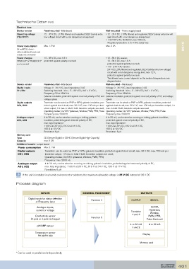
Process diagram
INPUTS CONTROL FUNCTIONS* OUTPUTS
Digital inputs for status detection
or Frequency input Function 1 OUTPUT SIGNAL
Analogue inputs, On/Off,
current or voltage ... Transistor Hysteresis,
1 and 2 Window,
Conductivity sensor PWM, PFM,
(2-pole or 4-pole technique) Function 6 Pulse (Mainboard)
4 to 20 mA 4 to 20 mA
pH/ORP sensor
1 and 2
Temperature sensor Display
Pt100/Pt1000
Memory card
* Can be used in parallel and independently
401