
Page 406 - Bürkert
P. 406
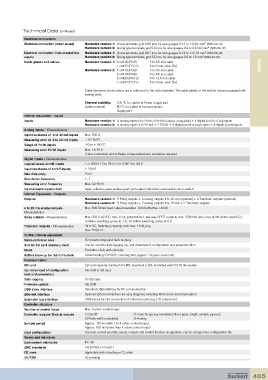
Technical Data (continued)
            Electrical connections
                                                                                            2
            Electrical connection power supply  Hardware version 1:  Screw terminals, grid 5.08 mm, for wire gauges 0.14 to 1.5/2.5 mm  (AWG 26-14)
                                                                                             2
                                       Hardware version 2:  Spring type terminals, grid 5.0 mm, for wire gauges 0.2 to 2.5/4.0 mm  (AWG 24-12)
                                                                                            2
            Electrical connection instrumentations   Hardware version 1:  Screw terminals, grid 3.81 mm, for wire gauges 0.14 to 1.0/1.5 mm  (AWG 26-16)
            supply                     Hardware version 2:  Spring type terminals, grid 3.5 mm, for wire gauges 0.2 to 1.5 mm  (AWG 24-16)
                                                                                           2
            Cable glands and cables    Hardware version 1:  9 x M16 (PG9)      5 to 6.5 mm cable
                                                     1 x M32 (PG21)   5 to 6 mm cable (5x)                           8620
                                       Hardware version 2:  4 x M16 (PG9)   5 to 6.5 mm cable
                                                     2 x M16 (PG9)   6 to 9.5 mm cable
                                                     3 x M20 (PG13)   9 to 13.5 mm cable
                                                     1 x M32 (PG21)   5 to 6 mm cable (5x)

                                       Cable diameters shown above are in reference to the outer diameter. The cable glands of the bottom row are equipped with
                                       sealing bolts
                                       Thermal stability:   105 °C for cables at Power Supply part
                                       (cable material)     80 °C for cables at Instrumentation
                                                     Supply part
            Internal equipment - Inputs
            Inputs                     Hardware version 1:  4 analog inputs (4 to 20 mA or Pt100) (software-configurable) + 4 digital (on/off or Freq) inputs
                                       Hardware version 2:  4 analog inputs 4 to 20 mA + 2 Pt100 + 4 digital (on/off or Freq) inputs + 4 digital (on/off) inputs
            Analog inputs - Characteristics
            Input resistance of  4 to 20 mA inputs  Max. 300 Ω
            Measuring error of  4 to 20 mA inputs  < 0.2 % FS
            Range of Pt100 inputs      -20 to +150 °C
            Measuring error Pt100 inputs  Max. ±0.25 K
                                       3 wire connection and software compensated wire resistance required
            Digital inputs - Characteristics
            Logical values on/off inputs  1 or HIGH: 13 to 35 V; 0 or LOW: 0 to 4.5 V
            Input resistance of on/off inputs  ≥ 20 kΩ
            Max. frequency             2 kHz
            Duty factor frequency      1 : 1
            Measuring error frequency  Max. 0.2 % FS
            Input accepts signals from  Open collector; open emitter; push-pull output; hall effect; reed switch; micro switch
            Internal Equipment - Outputs
            Outputs                    Hardware version 1:  5 Relay outputs + 4 analog outputs 4 to 20 mA (optional) + 4 Transistor outputs (optional)
                                       Hardware version 2:  5 Relay outputs + 2 analog outputs 4 to 20 mA + 2 Transistor outputs
            4 to 20 mA analog outputs -    Max. 500 Ohmic load, output resolution 10 bit (effective >9 bit)
            Characteristics
            Relay outputs - Characteristics  Max. 250 V AC/DC, max. 10 A, potential-free, two-way SPDT contacts, max. 2500 VA (AC), max 40 W Ohmic load (DC),
                                       3 million switching cycles at 1 A, 10 million switching cycles at 0 A
            Transistor outputs - Characteristics  24 V DC, Switching capacity each max. 16 W, pnp,
                                       max. 2200 Hz
            Further internal equipment
            Micro-controller core      32 bit with integrated flash memory
            Slot for SD card (memory card)  Can be used for data logging, up- and download of configuration and parameter files
            Clock                      Real-time clock with calendar
            Battery back-up for real-time clock  Lithium battery CR2032, exchangeable, approx. 10 years service life
            Communication
            SD card                    SD card capacity: minimum 64 MB, maximum 2 GB, formatted with FAT16 file system
            Up-/download of configuration    Via USB or SD card
            data and parameters
            Data-logging               On SD card
            Firmware update            Via USB
            USB slave interface        Standard USB interface for PC communication
            Ethernet interface         Optional: Ethernet interface for easy diagnosis including Web Server and email option
            Extension bus interface    CAN-based bus for connection of extension units (e.g. I/O extensions)
            Controller structure
            Number of control loops    Max. 8 active control loops
            Controller outputs/Module outputs  1) On/off         2) Pulse frequency modulated (fixed pulse length, variable pauses)
                                       3) Pulse width modulated    4) Analog
            Sample period              Approx.   50 ms (with 1 to 4 active control loops);
                                       Approx. 100 ms (more than 4 active control loops)
            User configuration         Cascade control possible; inputs, outputs and control function designations can be changed via configuration file
            Norms and standards
            Environment standards      IEC 68
            EMC standards              EN 61000, EN 55011
            CE mark                    Applicable tests resulting in CE mark
            UL/CSA                     UL pending


                                                                                                                 405