
Page 407 - Bürkert
P. 407
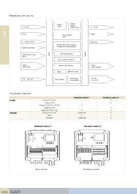
Hardware Structure


                                                              Graphic
                                                   Keypad     Display
                    4 ... 20 mA                    5 Keys     128 x 64 dots     4 ... 20 mA
      8620           Pt100                             Microcontroller          Relays


                                                       32 bit
                     4 ... 20 mA / Pt100                                        Transistors
                                                  SD Card Slot for Data Logging,
                                                  Configuration, Parameterisation
                    Digital (on/off) Inputs
                                            Inputs   USB Slave Interface    Outputs
                    Digital (on/off or Freq)
                    Inputs
                                                   Ethernet Interface (Option)

                     Option:                        Extension Bus Interface     Option:
                     further Inputs                                             further Outputs
                                                   Battery   Real Time Clock


                                                             Power Supply       24 V DC
                     100 ... 240 V AC            Power Supply
                                                             for Transmitters   max. 25 W


         Hardware Version
                                                                 Hardware version 1       Hardware version 2
          Inputs                      Analog 4 to 20 mA                 –                        4
                                        Analog Pt100                    –                        2
                                   Analog 4 to 20 mA / Pt100            4                        –
                                       Digital (on/off)                 –                        4
                                     Digital (on/off or Freq)           4                        4
          Outputs                     Analog 4 to 20 mA             4 (optional)                 2
                                          Relay                         5                        5
                                         Transistor                 4 (optional)                 2


                               Hardware version 1                         Hardware version 2


                                Screw terminals                                  Spring type terminals


  406