
Page 246 - Bürkert
P. 246
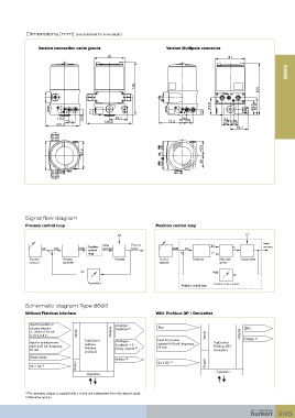
Dimensions [mm] (see datasheet for more details)


                 Version connection cable glands                    Version Multipole connector
                                             91                                              91
                                                                                                                     8693


                                                       156               84,0                            156                  43,5
                                                                                           4,2
                                                                                                                              38
                                                                                      51,8             43,3  51,8
                                      17,1                                         14,6
                        13,5      14,6          54,1                       13,5            9,3
      91                    31,7           135,8  91                 71,2   31,7           24,2 23,8
                        101,6
                                                                                                54,1


                 156               84,0                       156                  43,5
                                               4,2
                                                                                   38
                                          51,8              43,3  51,8
 17,1                                  14,6
 13,5  14,6  54,1              13,5             9,3
 31,7  135,8             71,2   31,7            24,2 23,8
 101,6                                               54,1


           Signal flow diagram
           Process control loop                                 Position control loop

                                                 Z2                                                 Z1
                                                                                                           Valve
                                                      Process
                                     Position  Valve                                  B1                   opening
                  SP   Xd2       CMD  control  opening  factor         CMD  Xd1                P K
                     +  -            loop                                 +  -        E1
             Process      Process              Process           Position      Positioner  Pilot valve   Control valve
             setpoint     controller                             setpoint                 system
                                  PV                                                   POS

                                    Transmitter                                        Position sensor system
                                                                          Position control loop


           Schematic diagram Type 8693
           Without Fieldbus interface                           With Profibus DP / DeviceNet

             Input for position or              Analogue
             process setpoint,                  feedback  2)     Bus                                Bus
             4 - 20mA, 0-20 mA  Inputs        Outputs
             0-10 V, 0-5 V                                                          Inputs        Outputs
                                   TopControl   Analogue         Input for process                  Initiator  2)
             Input for actual process  (without                  setpoint 4-20 mA, frequency,  TopControl
             value 4-20 mA, frequency,  Fieldbus  feedback + 2   Pt 100                Profibus DP /
             Pt 100                             binary outputs  2)                     DeviceNet
                                   interface)
             Binary inputs
                                                Initiator  2)         1)
             24 V DC  1)        Supply                           24 V DC            Supply
                                    Operation                                           Operation


           1)   The operating voltage is supplied with a 3-wire unit independent from the setpoint signal.
           2)  Alternative options

                                                                                                                 245