Page 288 - Bürkert
P. 288

Ordering chart
                                                                                Item no.               Item no.
                                                                     Item no.    8802-GD-J   Item no.    8802-GD-J
                                                          Pressure   8802-GD-              8802-GD-
                                 Port    Actuator   Kv value                    with posi-             with posi-
            Control   Orifice      connection   size   water    range to    I with   tioner and   I with   tioner and
              function  [mm]                               +185 °C      positioner           positioner
                                thread    Ø [mm]   [m /h]                     Process con-            Process con-
                                                     3
                                                            [bar]     8692     troller 8693   8692    troller 8693
                                                                   Steel/Steel             Steel/PTFE
                                                                               Steel/Steel            Steel/PTFE
            8802 GD-I and 8802 GD-J
            A 2/2-way   15      Flange      70      4.3      16      225 353    232 010     229 667     232 217       ELEMENT
            valve nor-       DIN EN 1092-1                                                                          8802 GD-I/GD-J
            mally closed   20   Flange      70      7.1      16      219 164    229 461     232 262     232 342
                             DIN EN 1092-1
            (NC)
                        25      Flange      90      12       16      229 422    229 462     266 884       –
                             DIN EN 1092-1
                        32      Flange      90     13.6      16      219 166    229 464     236 168     276 578
                             DIN EN 1092-1
                        40      Flange     130     23.8      16      229 423    229 465     260 905     277 569
                             DIN EN 1092-1
                        50      Flange     130      37       16      229 424    229 467     232 750     238 259
                             DIN EN 1092-1


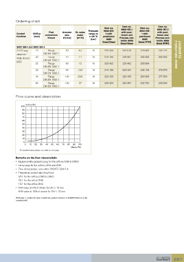
           Flow curve and description


                  Kv/Kvs [%]
               100
               90
               80
               70
               60
               50
               40
               30
               20
               10
                0
                 0  10  20  30  40  50  60  70  80  90  100
                                               Stroke [%]
              For detailed values please see table on next page

           Remarks on the flow characteristic
           •  Equipercentile parabolic plug for the orifices DN8 to DN50
           •  Linear plug for the orifices DN4 and DN6
           •  Flow characteristic runs within DIN/IEC 534-2-4
           •   Theoretical control ratio (Kvs/Kvo):
             50:1 for the orifices DN8 to DN50
             25:1 for the orifice DN6
             10:1 for the orifice DN4
           •   KVR value at 5% of stroke for DN > 10 mm
             KVR value at 10% of stroke for DN ≤ 10 mm

           (KVR value = smallest Kv value at which the gradient tolerance to DIN/IEC 534-2-4 is still
           complied with)


                                                                                                                 287
   283   284   285   286   287   288   289   290   291   292   293