
Page 290 - Bürkert
P. 290
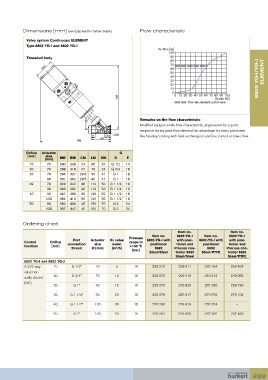
Dimensions [mm] (see datasheet for further details)  Flow characteristic

             Valve system Continuous ELEMENT
             Type 8802 YG-I and 8802 YG-J
                                                                       Kv /Kvs [%]
                                                                            100
             Threaded body                                                   90
                                                                             80
                                                                             70
                    Ø91                                                      60
                                                                             50                                       ELEMENT
                                                                             40                                     8802 YG-I/YG-J
                                                                             30
                                                                             20
                                                                             10
                                                                             0
                                                     HM                        0 10 20 30 40 50 60 70 80 90 100
                                                                                                 Stroke [%]
                                                                                    Flow rate standard control valve


                                       45°                     Remarks on the flow characteristic
                                                               Modified equipercentile flow characteristic, engineered for a quick
                                        D
                                                                 response during peak flow demand (an advantage for many processes
                                          E     CM  SW         like heating/cooling with heat exchangers) and fine control at lower flow.
                                              LM
                                   BM
             Orifice   Actuator                       G
             [mm]    size
                     [mm]   HM  BM   CM  LM   SW    D    E
              15      70    280  308  24  65  27   G 1/2  14
              20      70    288  318  27  75  34   G 3/4  16
              25      70    294  327  29.5  90  41  G 1  18
                      90    331  362  29.5  90  41  G 1  18
              32      70    302  342  36  110  50  G 1 1/4  16
                      90    345  382  36  110  50  G 1 1/4  16
              40      90    347  383  35  120  55  G 1 1/2  18
                     130    384  419  35  120  55  G 1 1/2  18
              50      90    360  406  45  150  70  G 2   24
                     130    397  442  45  150  70  G 2   24


           Ordering chart

                                                                                Item no.               Item no.
                                                                     Item no.   8802-YG-J   Item no.   8802-YG-J
                                                          Pressure
                                  Port   Actuator   Kv value      8802-YG-I with   with posi-  8802-YG-I with   with posi-
            Control    Orifice      connection   size   water    range to   positioner   tioner and   positioner   tioner and
              function  [mm]                               +185 °C
                                 thread   Ø [mm]   [m /h]             8692    Process con-   8692     Process con-
                                                     3
                                                            [bar]
                                                                   Steel/Steel  troller 8693   Steel/PTFE  troller 8693
                                                                               Steel/Steel            Steel/PTFE
            8802 YG-I and 8802 YG-J
            A 2/2-way    15      G 1/2”     70      5        16      229 270    228 611     232 164     259 464
            valve nor-
            mally closed   20    G 3/4”     70      10       16      229 272    229 415     240 343     249 255
            (NC)
                         25       G 1”      90      16       16      229 279    249 829     267 356     256 739
                         32     G 1 1/4”    90      23       16      229 275    229 417     273 975     273 104

                         40     G 1 1/2”   130      36       16      229 280    229 419     267 374       –
                         50       G 2”     130      53       16      229 281    229 420     267 362     247 460


                                                                                                                 289