
Page 314 - Bürkert
P. 314
Technical Data (continued)
Output Standards, directives and approvals
Standard signal ver- Protection class IP65 with cable plug or gland mounted and tightened
sion (according to EN60529) or with obturator locked if not used
Signal current 4... 20 mA (3-wire with relays; 2-wire without relay)
max. loop impedance: 900 Ω at 30 V DC, Standards and
600 Ω at 24 V DC, 50 Ω at 12 V DC, directives Complying with article 3 of chap. 3 from 97/23/CE
800 Ω with a 115/230 V AC voltage supply Pressure directive* 8025
Pulse Polarized, potential free, 5... 36 V DC; 100 mA, Standard
protected, line drop at 100 mA: 2.5 V DC EMC EN 61000-6-2, EN 61000-6-3
Relay 2 relays, freely configurable, 3 A, 230 V AC Safety EN 61010-1
Battery indicator/ None Vibration EN 60068-2-6
totalizer version Shock EN 60068-2-27
4... 20 mA measure- ±1% * F.S.=Full scale (10 m/s) INSERTION COMPACT
ment error 1) with Battery version = 100 °C (212°F)
2) Under reference conditions i.e. measuring fluid=water, ambient and water tempera-
Environment
ture=20 °C (68°F), applying the minimum inlet and outlet pipe straights, matched inside pipe
Height above sea level Max. 2000 m dimensions.
Relative humidity ≤ 80%, without condensation
Ambient temperature -10 to +60 °C (32 to 140°F) (version 12 - 36 V DC)
(operation and storage) -10 to +50 °C (32 to 122°F) (version 115/230 V AC) Type of fluid Conditions
Technical specifications 115/230 V AC Fluid group 1, chapter 1.3.a DN25 only
Voltage supply 27 V DC regulated, max. current: 125 mA Fluid group 2, chapter 1.3.a DN ≤ 32, or
available inside the integrated protection: fuse 125 mA temporised DN > 32 and PN*DN ≤ 1000
device power: 3 VA Fluid group 1, chapter 1.3.b PN*DN ≤ 2000
Fluid group 2, chapter 1.3.b DN ≤ 200 50 x DN 5 x DN
* For the 97/23/CE pressure directive, the device can only be used under following conditions
(depend on max. pressure, pipe diameter and fluid).
Installation
40 x DN 5 x DN
The Type 8025 can easily be installed into any Bürkert INSERTION fitting system (S020) by just fixing the main nut.
Minimum straight upstream and downstream distances must be observed. According to the pipe’s design, necessary distances can be bigger or use a
flow conditioner to obtain the best accuracy. For more information, please refer to EN ISO 5167-1.
25 x DN 5 x DN
50 x DN 5 x DN
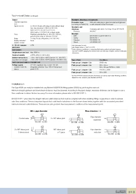
EN ISO 5167-1 prescribes the straight inlet and outlet distances that must be complied with when installing fittings in pipe lines in order to achieve
calm flow conditions. The most important layouts that could lead to turbulence in the flow are shown below, together with the associated prescribed
minimum inlet and outlet distances. These ensure calm, problem-free measurement conditions at the measurement point.
DN = pipe diameter 40 x DN 5 x DN Flow direction --> 20 x DN 5 x DN
Pipe diameter
Control valve 2 x 90° elbow joint
expansion
50 x DN 5 x DN 25 x DN 5 x DN 18 x DN 5 x DN
2 x 90° elbow joint 90° elbow joint Pipe diameter
3 dimensional or T-piece reduction
40 x DN 5 x DN 20 x DN 5 x DN 15 x DN 5 x DN
25 x DN 5 x DN 18 x DN 5 x DN
20 x DN 5 x DN 15 x DN 5 x DN
18 x DN 5 x DN
15 x DN 5 x DN
313