
Page 315 - Bürkert
P. 315
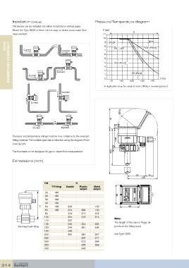
Installation (continued)                            Pressure/Temperature diagram
         The device can be installed into either horizontal or vertical pipes.
         Mount the Type 8025 in these correct ways to obtain an accurate flow   P (bar)
                                                                                     A
         measurement.                                             11
                                                                  10
     8025       Correct                 Incorrect                  8 7   PVC + PP          PVDF (PN10)
                                                                   9  PVDF                     Metal
       INSERTION COMPACT             Incorrect                     6 5 4 3 2  PVC (PN10)  PP (PN10)


                                                                   1
                   Correct
                                                                                                      T (°C)
                                                                   0
                                                                                   +30
                                                                                                +70
                                                                            +10
                                                                      -10
                                                                                         +50
                                                                   A: Application range for complete device (fitting + measuring device)
                                        Incorrect

                    Correct                                                 R 90


                      Correct           Incorrect                     91  (21)

         Pressure and temperature ratings must be in accordance to the selected
         fitting material. The suitable pipe size is selected using the diagram Flow/  85.5
         Velocity/DN.
                                                                        164.50          (30)
         The flowmeter is not designed for gas or steam flow measurement.  203

         Dimensions  [mm]


                                                                                       82     70
                                                                                          136
                             DN                  H
                                  T-Fitting  Saddle  Plastic   Metal
                                                   spigot   spigot
                             20    185
                             25    185                                    88
                             32    188
                             40    192
                           H  50   198      223              193                  88
                             65    198      221     206      199
                             80             226     212      204
                             100            231     219      214         Note:
                             110            227
                             125            234     254      225         The length of the sensor finger de-
            Total height with fitting  150  244     261      236         pends on the fitting used.
                             180            268
                             200            280     282      257         see Type S020.
                             250                    300      317
                             300                    312      336
                             350                    325      348
                             400                    340


  314