
Page 317 - Bürkert
P. 317
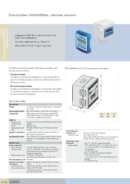
Transmitter UNIVERSAL, remote version


      UNIVERSAL,   remote version  •   Displays both flow rate and volume
   8025


               (with two totalizers)
            •   On site calibration by Teach-In
      Transmitter    •   Simulation of all output signals


         The 8025 universal flow transmitter with display, is available in wall-  Dimensions [mm] (see datasheet for further details)
         mounted and panel versions:

         •   The panel version
           is made up of an electronics integrated in an open housing with dis-
           play. The electrical connection is carried out on the terminal blocks of
           the electronic board

         •  The wall-mounted version                                                        B
           is made up of an electronics integrated in a housing with cover, display.
           The electrical connection is carried out on the terminal blocks of the
           electronic board via 3 cable glands.


         Technical data
          General data                                                                   A
          Display        15 x 60 mm, 8 digit LCD, alphanumeric, 15 segments,
                         9 mm high                                      C
          Recommended cable  Max. 50 m, shielded, 1.5 mm  max. cross-section
                                          2
          Compatibility  Bürkert flow sensor with frequency output (8020,                     A    B     C
                         8030, 8030HT, 8041, 8031, 8070, 8071) or other                      126   120   90
                         sensors with compatible electrical data.
          Materials
             Housing, cover   PC (panel-mounted version); ABS (wall-mounted version)
           Front panel foil   Polyester
           Screws        Stainless steel
           Cable glands/Cable   PA (wall-mounted version) / PA (panel-mounted
           clips         version)
                                                              Transmitter input
          Electrical connections  Terminals (panel-mounted version) or terminals via   (from sensor)  0.6 Hz to 2.2 kHz, can be adjusted -
                         gland (wall-mounted version)
                                                                 Frequency range  max. voltage: 36 V DC
                                  2
          Recommended cable  0.2 to 1.5 mm  cross-section, shielded cable, 4... 8 mm   Open collector NPN (with 470 Ω or 2.2 kΩ resistance)
                         diameter (for the cable glands of the wall-mounted   or PNP, Coil, TTL, CMOS (with 39 kΩ resistance)
                         version)
                                                              Transmitter output
          Electrical data                                     (to sensor)    - with a 12 - 36 V DC powered transmitter:
          Power supply (V+)                                      Voltage supply     • 10.5... 34.5 V DC [=(V+) - 1.5 V DC], 140 mA max.
             Panel- and wall-  12 - 36V DC (max tolerance: -5% or +10% at       •  0... 23.5 V DC [=(V+) - 12.5 V DC], 80 mA max.
           mounted version   12V VC; ±10% at 36 V DC), filtered and regulated,   non regulated
                         SELV (safety extra low voltage) circuit with a non      • 5 V DC, 30 mA max.
                         dangerous energy level,                             - with a 115/230 V AC powered transmitter:
           Wall-mounted version  115/230 V AC 50/60 Hz                          • +27 V DC, 80 mA max.
                         (see technical specifications 115/230 V AC)            • +14.5 V DC [=(V+) - 12.5 V DC] 80 mA max. non
          Reversal polarity of DC Protected                                   regulated
                                                                                • 5 V DC, 30 mA max.
          Current consumption   (without consumption of current output of the flow-
          with sensor    meter)
             Version with relay   ≤ 90 mA (at 12 V DC); ≤ 45 mA (at 36 V DC); ≤
           Version without relays  55 mA (115/230 V AC)
                         ≤ 60 mA (at 12 V DC); ≤ 30 mA (at 36 V DC); ≤
                         40 mA (115/230 V AC)


  316