
Page 323 - Bürkert
P. 323
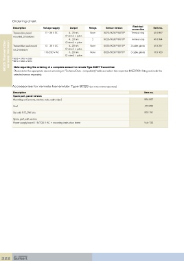
Ordering chart
                                                                                       Electrical
          Description        Voltage supply   Output       Relays     Sensor version                Item no.
                                                                                      connection
          Transmitter, panel   12 - 36 V DC   4... 20 mA    None    8020/8030 /8070 2)  Terminal strip  418 992
                                                                            1)
          mounted, 2 totalizers            (2 wires) + pulse
                                                             2
                                                                                      Terminal strip
                                              4... 20 mA    None    8020/8030 /8070 2) 2)  3 cable glands  418 994
                                                                            1)
     8025 Transmitter   remote Version  1)  8030 = SE30 + S030   115/230 V AC  (2 wires) + pulse  None  8020/8030 /8070 2)  3 cable glands  418 400
                                           (3 wires) + pulse
                                              4... 20 mA
                                                                                                    418 397
                              12 - 36 V DC
                                                                    8020/8030 /8070
                                                                            1)
          Transmitter, wall-mount-
          ed, 2 totalizers
                                              4... 20 mA
                                                                            1)
                                           (3-wires) + pulse
         2)  8070 = SE30 + S070
          Note regarding the ordering of a complete sensor for remote Type 8025T Transmitter:
          Please enter the appropriate sensor according to “Technical Data - compatibility” table and select the respective INSERTION fitting and order the
          selected sensor separately.
         Accessories for remote transmitter Type 8025 (has to be ordered separately)
          Description                                                                         Item no.
          Spare part, panel version
          Mounting set (screws, washer, nuts, cable clips)                                     554 807
          Seal                                                                                 419 350

          Set with 8 FLOW foils                                                                553 191

          Spare part, wall version
          Power supply board 115/230 V AC + mounting instruction sheet                         555 722


  322