
Page 326 - Bürkert
P. 326
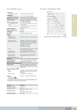
Technical Data (continued)                          Pressure / temperature chart

                                                                         Pressure (bar)
            Power supply                                                 12
               2 or 3 outputs transmitter   14-36 V DC, filtered and regulated   Metal + PVDF
             (2-wire)
            Electrical data
             4 outputs transmitter (3-wire)  12-36 V DC, filtered and regulated  10
            Characteristics of the power   Limited power source (according to § 9.3 of
            source (not provided) of UL   the UL61010-1 standard) or Class 2 type   PVC + PP                        8026
            recognized devices  power source (according to the 1310/1585   8
                                and 60950-1 standards)
            Current consumption with sensor ≤ 1 A (with transistors load)   6
               2 or 3 outputs transmitter   ≤ 25 mA (at 14 V DC without transistors load,
             (2-wire)           with current loop)                                               Metal
             4 outputs transmitter (3-wire)  ≤ 5 mA (at 12 V DC without transistors load,   4
                                without current loop)
                                                                                      PVC
            Power consumption   max. 40 W                                                       PVDF
            Reversed polarity of DC  Protected                            2
                                                                                            PP
            Voltage peak        Protected
            Short circuit       Protected for transistor outputs          0
            Output                                                        -20  0  20  40  60  80  100  120
               Transistor                                                                          T (°C)
             1 Transistor output    NPN, open collector, 1–36 V DC, max. 700 mA   Application range for complete device (Fitting + Transmitter)
             (Transmitter 2-wire)

               2 Transistor outputs    Configurable as sourcing or sinking (respec-
             (Transmitter 2 or 3-wire)   tively both as PNP or NPN ), open collector,
                                max. 700 mA, 0.5 A max. per transistor if the
                                2 transistor outputs are wired
                                NPN-output: 1 - 36 V DC
                                PNP-output: Power supply

             Current            4-20 mA programmable as sourcing or sinking
                                (in the same mode as transistor),
             1 Current output    max. loop impedance: 1100 W at 36 V DC ;
             (Transmitter 2-wire)   610 W at 24 V DC; 180 W at 14 V DC

             2 Current outputs    max. loop impedance: 1100 W at 36 V DC;
             (Transmitter 3-wire)  610 W at 24 V DC; 100 W at 12 V DC
            4...20 mA measurement error  ±1%
            Environment
            Ambient temperature  -10 °C to +60 °C (operating and storage)
            Relative humidity   ≤ 85%, without condensation
            Standards, directives and approvals
            Protection class    IP65, IP67, NEMA250 4X with M12 cable
                                plug mounted and tightened and cover fully
                                screwed down
            Standard and directives
               EMC              EN 61000-6-2 (2005), EN 61000-6-3 (2001)
             Pressure           Complying with article 3 of §3 from 97/23/
                                CE. directive*
             Vibration / Shock  EN 60068-2-6 / EN 60068-2-27

            Approvals           UL61010-1 + CAN/CSA-C22 No.61010-1
               UL-Recognized for
             US and Canada
            *  For the 97/23/CE pressure directive, the device can only be used under following condi-
             tions (depend on max. pressure, pipe diameter and fluid).


            Type of fluid       Conditions
            Fluid group 1, §1.3.a  DN ≤ 25 only
            Fluid group 2, §1.3.a  DN ≤ 32
                                DN > 32 and PN*DN ≤ 1000
            Fluid group 1, §1.3.a  DN ≤ 25
                                DN > 25 and PN*DN ≤ 2000
            Fluid group 2, §1.3.a  DN ≤ 400


                                                                                                                 325