
Page 321 - Bürkert
P. 321
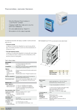
Transmitter, remote Version


     8025 Transmitter   remote Version  •   Only for Bürkert flowmeters in


               „Low Power“ version
            •   Displays both flow rate and volume
               (with two totalizers)
            •  On site calibration by Teach-In
            •  Simulation of all output signals


         The 8025 flow transmitter with display, is available in wall-mounted and   Dimensions [mm] (see datasheet for further details Details)
         panel versions:

         •   The panel version
           is made up of an electronics integrated in an open housing with dis-
           play. The electrical connection is carried out on the terminal blocks of
           the electronic board
                                                                                            B
         •   The wall-mounted version
           is made up of an electronics integrated in a housing with cover, display.
           The electrical connection is carried out on the terminal blocks of the
           electronic board via 3 cable glands.


         Technical data
                                                                                        A
          General data
          Display        15 x 60 mm, 8 digit LCD, alphanumeric,
                         15 segments, 9 mm high                        C
          Compatibility  Bürkert flow sensor with frequency output 8020, 8030
                         or 8070 (pulse “Low Power” version).
          Materials
             Housing, cover   PC (panel-mounted version); ABS (wall-mounted version)
           Front panel foil   Polyester                                       Version        A     B    C
           Screws        Stainless steel                                      Mounting panel  88  88    25
           Cable glands/Cable   PA (wall-mounted version) / PA (panel-mounted version)  Wall-mounting  126  120  90
           clips
          Electrical connections  Terminals (panel-mounted version) or terminals via
                         cable gland (wall-mounted version)
          Recommended cable  0.2 to 1.5 mm  cross-section, shielded cable, 4... 8 mm
                                  2
                         diameter (for the cable glands of the wall-mounted   Digital outputs
                         version)                                Pulse       polarized, potential free, 5... 36 V DC; 100 mA,
          Electrical data                                                    protected, line drop at 100 mA: 2.5 V DC

          Power supply (V+)
             Panel-mounted version  12 - 36 V DC ±10%, filtered and regulated   Relay  2 relays, freely adjustable 3 A, 230 V AC
           Wall-mounted version  12 - 36 V DC ±10%, filtered and regulated or   Analogue output
                         115/230 V AC 50/60 Hz (see technical specifi-     Current  4... 20 mA (3-wire with relays; 2-wire without relay);
                         cations 115/230 V AC)                               max. loop impedance: 900 Ω at 30 V DC,
                                                                             600 Ω at 24 V DC, 50 Ω at 12 V DC,
          Reversal polarity of DC Protected
                                                                             800 Ω with a 115/230 V AC voltage supply
          Current consumption   (without consumption of pulse output)
          with sensor    ≤ 70 mA (at 12 V DC)                 4...20 mA measure-  ±1%
             Version with relay   ≤ 25 mA (at 12 V DC)        ment error
           Version without relays                             Technical      Wall-mounted version:
                                                              specifications   Supply voltage: 27V DC controlled,
          Transmitter input                                   115/230V AC    Max. current: 250 mA
          (from sensor)  2.5 to 400 Hz                        available on the device  Integrated protection: security fuse 250 mA
             Frequency range  Pulse “Low Power” (open collector NPN)         Power: 6 VA
          Transmitter output
          (to sensor)    10... 34 V DC (=(V+) - 2 V DC),
             Voltage supply   max. current available from transmitter: 1 mA
           Current consumption

  320