
Page 388 - Bürkert
P. 388
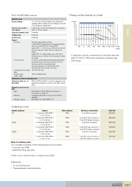
Technical Data (continued)                          Pressure/temperature chart
            Electrical data
            Supply voltage   12 - 36 V DC, ±10% oscillation rate, filtered and   P (bar)
                             regulated, SELV (safety extra low voltage) circuit with   12  A
                             a non dangerous energy level           11                             PEEK
            Current consumption    ≤ 25 mA (at 12 V DC and without the consumption   10 9
            with sensor      of the 4... 20 mA output)              8                   PVDF
            Reversed polarity of DC  Protected                      7                                                8228
            Voltage peak     Protected                              6
                                                                    5
            Short circuit    Protected                              4
            Output                                                  3
               Transistor    Polarized, galvanically insulated      2               PP
                             configurable through wiring and through parameter-  1 0
                             izing as sourcing (PNP) or sinking (NPN)  -20  0   +20  +40  +60  +80 +100 +120  +140
                             output NPN: 1 - 36 V DC, max. 700 mA (or 500 mA                             T (°C)
                             max. per transistor if both transistor outputs are
                             wired)
                             output PNP: V+ supply voltage, max. 700 mA (or
                             500 mA max. per transistor if both transistor outputs   A: Application range for complete device (conductivity meter with
                             are wired)                          either PP, PVDF or PEEK sensor inserted into a Stainless steel
             Current (3-wire)   4... 20 mA configurable through wiring and through   S020 fitting)
                             parameterizing as sourcing or sinking, 22 mA to
                             indicate a fault (can be parametered)
                             max. loop impedance: 1100 W at 36 V DC;
                             610 W at 24 V DC; 100 W at 12 V DC
             Uncertainty of the output  1% of the full scale
             value
             Response time    150 ms (default value)
             (10% - 90%)
            Standards, directives and approvals
            Protection class acc. to   IP65 and IP67 with M12 connectors plugged in and
            EN 60529         tightened and electronic module cover fully screwed
                             down
            Standard and directives
               EMC           EN 61000-6-2, EN 61000-6-3 and Annex1,
                             EN 61326-1-7 (Table 2)
             Pressure        Complying with article 3 of §3 from 97/23/CE
                             directive.*
             Vibration / Shock  EN 60068-2-6 / EN 60068-2-27

           Ordering Chart

            Holder material            Output            Seal material    Electrical connection    Item No
            PP                   1 x transistor NPN/PNP +    FKM           5-pin M12 connector     566 601
                                     1 x 4 to 20 mA
                                 2 x transistor NPN/PNP +    FKM         5-pin M12 male connector +   566 602
                                     2 x 4 to 20 mA                      5-pin M12 female connector
            PVDF                 1 x transistor NPN/PNP +    FKM           5-pin M12 connector     566 603
                                     1 x 4 to 20 mA
                                 2 x transistor NPN/PNP +    FKM         5-pin M12 male connector +   566 604
                                     2 x 4 to 20 mA                      5-pin M12 female connector
            PEEK                 1 x transistor NPN/PNP +    FKM           5-pin M12 connector     566 605
                                     1 x 4 to 20 mA
                                 2 x transistor NPN/PNP +    FKM         5-pin M12 male connector +   566 606
                                     2 x 4 to 20 mA                      5-pin M12 female connector
           Note for ordering chart:
           For a complete conductivity unit the following items must be ordered:
           - Transmitter Type 8228
           - INSERTION Fitting Type S020

           Further versions and information see datasheet type 8228.

           Options

           •  UL and CSA approvals
           •  Preparameterized conductivity meters


                                                                                                                 387