
Page 413 - Bürkert
P. 413
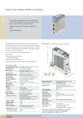
Mass Flow Meter (MFM) for Gases


      8702  •   Direct flow measurement with CMOS-

                   ®
               ens  technology for nominal flow rates
               from 20 mlN/min to 80 lN/min
            •   High accuracy and quick response
               time
            •  Optional fieldbus


         The digital mass flow meter, Type 8702, uses a sensor on silicon chip   Dimensions [mm] (see datasheet for more details)
         basis located directly in the bypass channel. Due to the fact that the sen-
         sor is directly in the bypass chan nel a very fast response time of the MFM
         is reached. The actual flow is given as an analog output signal or could be
         read out over fieldbus communication.
         Typical application areas are gas flow measurement in
         • Test benches                                              C
         • Packaging and foodstuff industry
         • Environmental technology
         • Pharmaceutical and Biotechnology
         In particular, Type 8702 fulfils the requirements of IP65 protection.


         Technical Data
          Nominal flow range   (Q  )  0.01 to 80 l /min  (ref. to N )
                                        2)
                      1)
                         nom        N         2
          Turn-down ratio    1:50, wider span on request
          Operating gas      Neutral, non-contaminated                          A
                             gases, others available on request
          Calibration gas    Operating gas or air with correcting function
                                                                  A     B    C
          Max. operating pressure  Up to max. 10 bar (145 psi),   115  37   137                       B
          (Inlet pressure)   depending on the orifice of the valve
          Gas temperature    -10 to +70°C (-10 to +60°C with oxygen)
          Ambient temperature  -10 to +50°C (others on request)
          Accuracy           ±0.8% o.R. ±0.3% F.S.
          (after 1 min warm up time)  (o.R.: of reading; F.S.: of full scale)  Digital communication    RS232, Modbus RTU (via RS interface)
                                                                                 RS485, RS422 or USB
          Repeatability      ±0.1% F.S.                       via adapter possible:    (see accessories table)
          Settling time (t 95% )  <300 ms                     Fieldbus option    Profibus-DP, DeviceNet, CANopen
          Materials                                                              (D-Sub HD15 covered with sealed plate with
             Body            Stainless steel                                     fieldbus MFC)
            Housing          PC (Polycarbonate)               Type of protection    IP65
            Seals            FKM, EPDM (others on request)    (with connected cables)
          Port connection    G 1/4” (others on request)
                                                              Total weight       1000 g
          Electr. connection  Socket M16, round, 8-pin and
                             socket D-Sub HD15, 15-pin        Mounting position  Horizontal or vertical
          Additionally with fieldbus:   With PROFIBUS-DP:     Light emitting diodes  Indication for Power, Communication, Limit,
                             Socket M12 5-pin (for IP65) or D-Sub 9-pin    (Default, other functions   Error
                             With DeviceNet/CANopen:            programmable)
                             Plug M12 5-pin (for IP65) or D-Sub 9-pin  Binary inputs  Three various functions programmable
          Operating voltage  24V DC                           (Default, other functions
          Voltage tolerance  ±10%                               programmable)
          Residual ripple    <2%                              Binary outputs     Two relay outputs
                                                              (Default, other functions   1.  Limit (Qnom almost reached)
          Power consumption  max. 2.5 W (analog communicator)                    2. Error (i.e. sensor fault)
                             to 5 W (digital communicator)      programmable)    Load capacity: max. 60 V, 1 A, 60 VA
          Output signal (signal output)  0–5 V, 0–10 V, 0–20 mA or 4–20 mA
            Max. current, volt. output  10 mA                1)   The nominal flow value is the max. flow value calibrated which can be controlled.
            Max. load, current output  600 Ω                  The nominal flow range defines the range of nominal flow rate possible.
                                                             2)   Index N: Flow rates referred to 1.013 bar(a) and 0 ºC, alternatively also
                                                              Index S: Flow rates referred to 1.013 bar(a) and +20 ºC.

  412