
Page 89 - Bürkert
P. 89
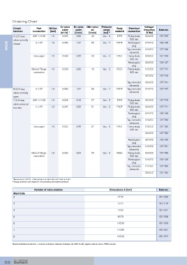
Ordering Chart
                                       Kv value   Kv value   QNn-value  Pressure             Voltage/
          Circuit       Port    Orifice   water   water    air     range   Body    Electrical   frequency   Item no.
            function    connection  [mm]                                    material  connection
                                        [m /h]  1)  [l/min]  [l/min]  [bar]  2)               [V/Hz]
                                          3
          A 2/2-way   UNF 1/4-28  1.5    0.039    0.66     42      Vac. - 2  ETFE  Flying leads,   024/DC  137 759
                                                                                    500 mm
          valve normally   G 1/8”  1.6   0.060    1.02     65      Vac. - 2  PVDF  Rectangular   024/DC  139 146
      6606  closed                                                                   plug
                                                                                  Tag connector
                                                                                   sidewards  024/DC  137 746
                      Tube spigot  1.6   0.039    0.66     42      Vac. - 2  PVDF  Flying leads,   024/DC  137 764
                                                                                    500 mm
                                                                                   Rectangular   024/DC  139 147
                                                                                     plug
                     Bürkert Flange   1.6  0.039  0.66     42      Vac. - 2  PEEK  Flying leads,   012/DC  137 744
                      connection                                                    500 mm
                                                                                             024/DC   137 745
                                                                                  Tag connector   024/DC  137 741
                                                                                   sidewards
          B 2/2-way     G 1/8”    1.6    0.060    1.02     65      Vac. - 2  PVDF  Tag connector   024/DC  137 747
          valve normally                                                           sidewards
          open
          T 3/2-way   UNF 1/4-28  1.5    0.025    0.43     27      Vac. - 2  ETFE  Flying leads,   024/DC  137 779
          valve universal                                                           500 mm
          function      G 1/8”    1.6    0.047    0.80     51      Vac. - 2  PVDF  Flying leads,   024/DC  137 771
                                                                                    500 mm
                                                                                   Rectangular   024/DC  139 149
                                                                                     plug
                                                                                  Tag connector   024/DC  137 769
                                                                                   sidewards
                      Tube spigot  1.6   0.025    0.43     27      Vac. - 2  PVDF  Flying leads,   012/DC  137 782
                                                                                    500 mm
                                                                                             024/DC   137 783

                                                                                   Rectangular   024/DC  139 150
                                                                                     plug
                                                                                  Tag connector   012/DC  137 781
                                                                                   sidewards
                     Bürkert Flange   1.6  0.032  0.54     35      Vac. - 2  PEEK  Flying leads,   024/DC  137 768
                      connection                                                    500 mm
                                                                                   Rectangular   024/DC  139 148
                                                                                     plug
                                                                                  Tag connector   012/DC  137 766
                                                                                   sidewards
                                                                                             024/DC   137 765

         1)  Measured at +20 °C , 2 bar pressure at valve inlet and 1 bar at outlet
         2)  Gauge pressure with respect to the prevailing atmosphere pressure

                       Number of valve stations                        Dimensions A [mm]              Item no.
          Manifolds
          2                                                                 37.50                     651 506
          3                                                                 53.75                     651 510

          4                                                                 70.25                     651 507

          5                                                                 86.75                     651 508
          6                                                                103.30                     651 509

          7                                                                119.80                     651 521
          8                                                                163.30                     651 522

         Standard distributor/collector: a common In/Output, individual Out/Input (all UNF1/4-28) supplied without valves; PEEK material


    88