
Page 329 - Bürkert
P. 329
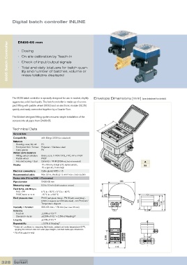
Digital batch controller INLINE


      8035 Batch Controller  DN06-65 mm


            •   Dosing
            •   On site calibration by Teach-In
            •   Check of input/output signals
            •   Total and daily totalizers for batch quan-
               tity and number of batches, volume or
               mass totalizers displayed


         The 8035 batch controller is specially designed for use in neutral, slightly   Envelope Dimensions [mm] (see datasheet for details)
           aggressive, solid-free liquids. The batch controller is made up of a com-
         pact fitting with paddle-wheel (S030) and an electronic module (SE35)
         quickly and easily connected together by a Quarter-Turn.

         The Bürkert designed fitting system ensures simple installation of the
         sensors into all pipes from DN06-65.
                                                                    A
         Technical Data

          General data
          Compatibility    with fittings S030 (see datasheet)
          Materials
             Housing, cover, lid, nut   PC
           Front panel foil / Screws   Polyester / Stainless steel
           Cable glands    PA
          Wetted parts materials
             Fitting, sensor armature   Brass, st, st, 1.4404/316L, PVC, PP or PVDF
           Paddle-wheel    PVDF
           Axis and bearing / Seal  Ceramics / FKM (EPDM incl., but not mounted)             A
          Display          15 x 60 mm, 8 digit LCD, alphanumeric,                            88
                           15 segments, 9 mm high
          Electrical connections  Cable glands M20 x 1.5
          Recommended cable  Max. 50 m, shielded, 1.5 mm  max. cross-section
                                            2
          Device data (Fitting S030 + Electronics)
          Pipe diameter    DN06-65 mm                                        180
          Measuring range  0.3 to 10 m/s (Hall transducer version)
          Fluid temp. with fitting in
             PVC / PP      0 °C to +50 °C / 0 °C to +80 °C        91
           PVDF, brass or st. st.  -15 °C to +100 °C                21
          Fluid pressure max.  PN10 (with plastic fitting) - PN16 (with metal fitting) -                      88
                           (PN40 on request, see S030 data sheet) - see Pressure/        105          75
                           Temperature diagram                                                          104  114
          Viscosity / Pollution  300 cSt. max. / 1% max (size: max. 0.5 mm)
                                                                                                                    116
          Accuracy
             Teach-In      ±0.5% of F.S.*
                                    1)
           Standard K-factor  ±(0.5% of F.S.* + 2.5% of Reading) 1)
                                   180
          Linearity        ±0.5% of F.S.* 1)
          Repeatability    ≤ 0.4% of Reading 1)
          1)   Under ref. conditions i.e. measuring fluid=water, ambient and water temperature=20 °C,
                        91
             applying the minimum inlet and outlet pipe straights, matched inside pipe dimensions.
          *  F.S.=Full scale (10 m/s)  21
                                                105          75  104  114  88

                                                                          116


  328