
Page 442 - Bürkert
P. 442
Technical Data (continued)
Electrical data
Power supply
2 or 3 outputs transmitter (2-wire) 14-36 V DC, filtered and regulated
4 outputs transmitter (3-wire) 12-36 V DC, filtered and regulated
Characteristics of the power source Limited power source (according to § 9.3 of the UL61010-1 standard)
(not provided) of UL recognized or, Class 2 type power source (acc. to the 1310/1585 and 60950-1
devices standards) SE36
Current consumption with sensor ≤ 1 A (with transistors load)
2 or 3 outputs transmitter (2-wire) ≤ 25 mA (at 14 V DC without transistors load, with current loop)
4 outputs transmitter (3-wire) ≤ 5 mA (at 12 V DC without transistors load, without current loop)
Power consumption 40 W max.
Reversed polarity of DC Protected
Voltage peak Protected
Short circuit Protected for transistor outputs
Output
Transistor
1 Transistor output NPN, open collector, 1 - 36 V DC,
(Transmitter 2-wire) max. 700 mA
2 Transistor outputs Configurable as sourcing or sinking (respectively both as PNP or NPN ),
(Transmitter 2 or 3-wire) open collector, max. 700 mA, 500 mA max. per transistor if the 2
transistor outputs are wired
NPN-output: 1 - 36 V DC
PNP-output: Power supply
Current 4-20 mA programmable as sourcing or sinking (in transistor mode),
1 Current output (Transmitter 2-wire) max. loop impedance: 1100 Ω at 36 V DC ;
610 Ω at 24 V DC; 180 Ω at 14 V DC
2 Current outputs max. loop impedance: 1100 Ω at 36 V DC;
(Transmitter 3-wire) 610 Ω at 24 V DC; 100 Ω at 12 V DC * For the 97/23/CE pressure directive, the device can only be
4 to 20 mA measurment error ±1% used under following conditions (depend on max. pressure,
pipe diameter and fluid).
Standards, directives and approvals
Protection class IP65, IP67, NEMA 4X and NEMA 6P with M12 cable plug mounted Type of fluid Conditions
and tightened and cover fully screwed down Fluid group 1, §1.3.a DN ≤ 25 only
DN ≤ 32
Standard and directives Fluid group 2, §1.3.a
EMC EN 61000-6-2 (2005), EN 61000-6-3 (2001) DN > 32 and PN*DN ≤ 1000
Pressure Complying with article 3 of §3 from 97/23/CE. directive* Fluid group 1, §1.3.a PN*DN ≤ 2000
Vibration / Shock EN 60068-2-6 / EN 60068-2-27 Fluid group 2, §1.3.a DN ≤ 200
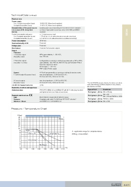
Pressure / Temperature Chart
P (bar) A
16
15 Metal
14
13
12
11
10
9 PVDF A : application range for complete device
8
7 PVC + PP PVDF (PN10) (Fitting + transmitter)
6
5
4 PVC (PN10)
3
2
1 PP (PN10)
0 T °C
-30 -10 +10 +30 +50 +70 +90 +110
441