
Page 439 - Bürkert
P. 439
50 x DN 5 x DN
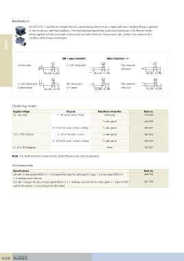
Installation
40 x DN 5 x DN
EN ISO 5167-1 specifies the straight inlet and outlet distances that must be complied with when installing fittings in pipelines
in order to achieve calm flow conditions. The most important layouts that could lead to turbulence in the flow are shown
below, together with the associated minimum inlet and outlet distances. These ensure calm, problem-free measurement
conditions at the measurement point. 25 x DN 5 x DN
SE35 50 x DN 5 x DN
Fluid direction -->
DN = pipe diameter 40 x DN 5 x DN 20 x DN 5 x DN
Control valve 2 x 90° elbow joint Pipe diameter
extension
50 x DN 5 x DN 25 x DN 5 x DN 18 x DN 5 x DN
2 x 90° elbow joint 90° elbow joint Pipe diameter
3 dimensional or T-piece reduction
40 x DN 5 x DN 20 x DN 5 x DN 15 x DN 5 x DN
Ordering chart 25 x DN 5 x DN 18 x DN 5 x DN
Supply voltage Outputs Electrical connection Item no.
12 - 36 V/DC 4 - 20 mA (2 -wire) + Pulse Cable plug 444 005
20 x DN 5 x DN 15 x DN 5 x DN 444 006
2 cable glands
4 - 20 mA (3 -wire) + Pulse + Relays 2 cable glands 444 007
115 - 230 V/50 Hz 4 - 20 mA (2-wire) + Pulse 2 cable glands 423 922
18 x DN 5 x DN
4 - 20 mA (3 -wire) + Pulse + Relays 2 cable glands 423 924
2 x 9 V/ DC Batteries - None 423 921
15 x DN 5 x DN
Note: The SE35 electronic module and the S030 fitting must be ordered separately
Accessories
Specifications Item no.
Set with 2 cable glands M20x1.5 + 2 neoprene flat seals for cable gland or plug + 2 screw-plugs M20x1.5 449 755
+ 2 multiway seals 2x6 mm
Set with 1 stopper for unused cable gland M20x1.5 + 1 multiway seal 2x6 mm for cable gland + 1 black EPDM 551 775
seal for the sensor + 1 mounting instruction sheet
438