
Page 437 - Bürkert
P. 437
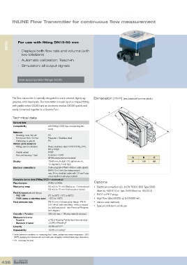
INLINE Flow Transmitter for continuous flow measurement


      SE35  For use with fitting DN15-50 mm


            •   Displays both flow rate and volume (with
               two totalizers)
            •   Automatic calibration: Teach-In
            •   Simulation: all output signals


             See appropriate fittings S030


         The flow transmitter is specially designed for use in neutral, slightly ag-  Dimension [mm] (see datasheet for more details)
         gressive, solid free liquids. The transmitter is made up of a compact fitting
         with paddle-wheel (S030) and an electronic module (SE35) quickly and
         easily connected together by a Quarter-Turn

         Technical data
          General data
          Compatibility         with fittings S030 (see corresponding data
                                sheet)
          Materials
             Housing, cover, lid, nut   PC
           Front panel foil / Screws   Polyester / Stainless steel
           Cable plug or glands  PA
          Wetted parts materials
             Fitting, sensor armature   Brass, stainless steel 1.4404/316L, PVC,
                                PP or PVDF
           Paddle-wheel         PVDF
           Axis and bearing / Seal  Ceramics / FKM
                                (EPDM included but non-mounted)                      A      B      C
          Display               15x60 mm, 8-digit LCD, alphanumeric,                 84    116     88
                                15 segments, 9 mm high
          Electrical connections  Cable plug EN175301-803 or cable glands
                                M20x1.5 or none (for battery version)
                                max. 50 m, shielded cable with 1.5 mm  max.
                                                      2
                                cross-section (cable plug included)
          Complete device data (Fitting S030 + electronics)
          Pipe diameter         DN06 to DN65                 Options
          Measuring range       0.5 m/s to 10 m/s (Battery ver. - Coil transducer)   •   Electrical connection acc. to EN 75301-803 Type 2508
                                0.3 m/s to 10 m/s (Hall transducer version)  (Item no. 438 811) or Type 2509 (Item no. 162 673)
          Fluid temperature with fitting in
             PVC / PP           0°C to 50°C / 0°C to 80°C)   •  PVDF or PP Fittings.
           PVDF, brass or stainless steel  -15°C to 100°C    •  High flow rates (8025) up to DN350 mm
          Fluid pressure max.   PN10 (145.1PSI) (with plastic fitting) - PN16   •  Various seal materials
                                (232.16PSI) ( with metal fitting - PN40 on request,   •  Special calibration certificate
                                see S030 data sheet) - see Pressure/Tempera-
                                ture diagram
          Viscosity / Pollution  300 cSt. max. / 1% max. (size: 0.5 mm max.)
          Measurement error
                                         1)
             Teach-In           ±1% of Reading (at the teach flow rate value)
           Standard K-factor    ±2.5% of Reading 1)
          Linearity             ±0.5% of F.S.* 1)
          Repeatability         ±0.4% of reading 1)
         1)   Under reference conditions i.e. measuring fluid=water, ambient and water temperature=20°C
          (68°F), applying the minimum inlet and outlet pipe straights, matched inside pipe dimensions
         *  F.S.=Full scale (10 m/s)


  436