
Page 438 - Bürkert
P. 438
Technical data (continued)
Electrical data
Power supply (V+)
Standard signal version 12-36 V DC ±10%, filtered and regulated, SELV (extra low
safety voltage) circuit with a non dangerous energy level or
115/230 V AC 50/60 Hz (see tech. spec. 115/230 V AC)
Battery indicator/totalizer version 2 x 9 V DC batteries, lifetime min. 1 year at 20°C
Reversed polarity of DC protected SE35
Current consumption with sensor ≤ 70 mA at 12 V DC - transmitter with relays
(without consumption of pulse output) ≤ 25 mA at 12 V DC - transmitter without relay
Output
Standard signal version
Signal current 4-20 mA (3-wire with relays; 2-wire without relay)
max. loop impedance: 900 Ω at 30 V DC;
600 Ω at 24 V DC; 50 Ω at 12 V DC;
800 Ω with a 115/230 V AC voltage supply
Pulse Polarized, potential free, 5 to 36 V DC; 100 mA,
protected, line drop at 100 mA: 2.5 V DC
Relay 2 relays, freely configurable, 3 A, 230 V AC
Battery indicator/totalizer version None
4 to 20 mA measurement error ±1%
Environment
Height above sea level max. 2000 m
Ambient temperature 0°C to +60°C (12-36 V DC or battery version)
(operation and storage) 0°C to +50°C (115/230 V AC version)
Relative humidity ≤ 80%, without condensation
Technical specifications 115/230 V AC * For the 2006/95/CE pressure directive, the device can only be
Voltage supply 27 V DC regulated, max. current: used under following conditions (depend on max. pressure, pipe
available inside the device 125 mAintegrated protection: diameter and fluid).
fuse 125 mA temporised power: 3 VA
Standard, directives and approvals Type of fluid Conditions
Protection class IP65 with cable plug or gland mounted and tightened or with Fluid group 1, §1.3.a
obturator locked if not used. DN25 only
Standard Fluid group 2, §1.3.a DN ≤ 32, or
EMC EN 61000-6-2, EN 61000-6-3 DN > 32 and PN*DN ≤ 1000
Safety EN 61010-1 Fluid group 1, §1.3.b
Pressure (Fitting S030, DN06 to DN65, in PN*DN ≤ 2000
PVC, PP, PVDF, stainless steel or brass) Complying with article 3 of chp. 3 from 2006/95/CE directive* Fluid group 2, §1.3.b
Vibration / Shock EN 60068-2-6 / EN 60068-2-27 DN ≤ 200
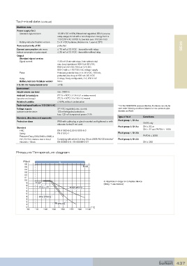
Pressure/Temperature diagram
P (bar) A
16
15 Metal
14
13
12
11
10 A: Application range for complete device
9 PVDF (fitting + electronics)
8 PVC + PP
7 PVDF (PN10)
6
5
4 PVC (PN10)
3
2
1 PP (PN10)
0 T °C
-30 -10 +10 +30 +50 +70 +90 +110
437