
Page 123 - Bürkert
P. 123
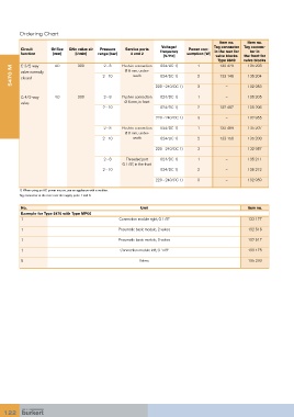
Ordering Chart
                                                                                          Item no.   Item no.
                                                                  Voltage/              Tag connector  Tag connec-
         Circuit      Orifice   QNn value air   Pressure    Service ports    frequency   Power con-  in the rear for   tor in
         function     [mm]     [l/min]   range [bar]  4 and 2                sumption [W]
                                                                   [V/Hz]               valve blocks   the front for
                                                                                         Type 8640  valve blocks
                                                                                                     135 203
                                                                  024/DC 1)
                                                                                 1
                       4.0
                                 300
                                                  Push-in connection
                                           2 - 8
                                                                                          132 479
         C 3/2-way
      5470 M  valve normally               2 - 10   Ø 6 mm, under-  220 - 240/DC 1)  2 3  133 148    135 204
                                                       neath
                                                                  024/DC 1)
         closed
                                                                                            –
                                                                                                     132 953
         G 4/2-way     4.0       300       2 - 8  Push-in connection    024/DC 1)  1        –        135 205
         valve                                     Ø 6 mm, in front
                                           2 - 10                 024/DC 1)      2        132 487    135 206
                                                                220 - 240/DC 1)  3          –        132 955
                                           2 - 8  Push-in connection    024/DC 1)  1      132 489    135 207
                                                    Ø 6 mm, under-
                                           2 - 10      neath      024/DC 1)      2        133 150    135 208
                                                                220 - 240/DC 1)  3          –        132 957
                                           2 - 8    Threaded port     024/DC 1)  1          –        135 211
                                                   G 1/8”, in the front
                                           2 - 10                 024/DC 1)      2          –        135 212

                                                                220 - 240/DC 1)  3          –        132 959

         1) When using an AC power source, use an appliance with a rectifier.
         Tag connector at the rear: over the supply ports 1 and 3.

          No.                                             Unit                                       Item no.
          Example for Type 5470 with Type MP05
          1                                      Connection module right, G 1/8”                     133 177
          1                                      Pneumatic basic module, 2 valves                    132 516

          1                                      Pneumatic basic module, 3 valves                    132 517

          1                                       Connection module left, G 1/8”                     133 175
          5                                              Valves                                      135 203


   122