
Page 214 - Bürkert
P. 214
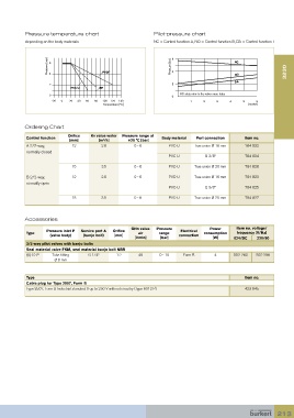
Pressure temperature chart                          Pilot-pressure chart
           depending on the body materials                     NC = Control function A, NO = Control function B, DA = Control function I


                    Pressure [bar]  6 4   PVDF                        Pressure [bar]  6 4       NC                   3230


                                                                                                NO
                                                                                                DA
                     2                                                 2
                              PVC-U      PP
                     0                                                 0  NC: data refer to the valves max. hubs
                      -20   0   20   40   60   80   100  120  140             1    2     3    4    5     6
                                           Temperature [ºC]                                           [stroke]


           Ordering Chart

                             Orifice   Kv value water   Pressure range at
            Control function                                       Body material  Port connection   Item no.
                                           3
                             [mm]        [m /h]      +20 °C [bar]
            A 2/2-way,        12          2.8          0 - 6         PVC-U      True union Ø 16 mm  784 822
            normally closed
                                                                     PVC-U          G 3/8”          784 824
                              15          3.5          0 - 6         PVC-U      True union Ø 20 mm  784 826

            B 2/2-way,        12          2.8          0 - 6         PVC-U      True union Ø 16 mm  784 823
            normally open
                                                                     PVC-U          G 3/8”          784 825
                              15          3.5          0 - 6         PVC-U      True union Ø 20 mm  784 827


           Accessories

                                                      QNn value   Pressure            Power      Item no. voltage/
                    Pressure inlet P   Service port A   Orifice           Electrical
            Type                                         air      range             consumption   frequency [V/Hz]
                     (valve body)  (banjo bolt)  [mm]                    connection
                                                        [l/min]   [bar]                [W]      024/DC   230/50
            3/2-way pilot valves with banjo bolts
            Seal material valve FKM, seal material banjo bolt NBR
            6012 P    Tube fitting    G 1/4”    1.2      48       0 - 10   Form B       4       552 283   552 286
                       Ø 6 mm


            Type                                                                                    Item no.
            Cable plug for Type 2507, Form B
            Type 2507, Form B Industrial standard 0 up to 250 V without circuitry (Type 6012 P)     423 845


                                                                                                                 213