
Page 431 - Bürkert
P. 431
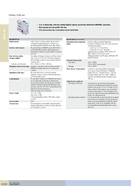
Safety Barrier


                                   •   2 or 4 channels, intrinsic safety digital inputs: proximity detectors NAMUR, contacts...
                                   •   Rail mount on hat profile 35 mm
      SE30 Ex
                                   •   All connections by removable screw terminals


          Specifications
          Digital inputs     Each of the 4 x intrinsic safety inputs can be   Specifications (continued)  Intrinsic safety associated apparatus.
                                                              Classification for explosive
                             configured independently for a contact or a   areas  It must be installed in safe area and connected
                             proximity detector NAMUR as per DIN 19234           to materials installed
          Intrinsic safety inputs  Proximity detector NAMUR as per DIN 19234         in zone 0, 1 or 2 - Gas (G) or
                             or free potential contacts, relays, pressure or      in zone 20, 21 or 22 - Dust (D)
                             temperature switches or push buttons in hazard-     Classification according to ATEX 94/9/CE:
                             ous area.                                              I/II (M1)/(1) G/D [EEx ia] IIC
          Non intrinsic safety  According to the type of sensor and the chosen   Safety parameters see EC-type certificate LCIE
          recopy outputs     logic: a green LED on the front panel displays a    00ATEX 6034X
                             free-potential contact for each channel without   Ambient Temperature
                             common wire.                       Operating        -20 to +60°C
            Collector cut-off power   15 V - 60 mA - 0.9 VA - 350 Hz             -20 to +50°C (recommended)
          Selection of the sensor type Inductive / capacitive intrinsic safety certified     Storage  -40 to +80°C
                             NAMUR proximity detector or free-potential   Dimensional & mechanical  Housing for symmetrical DIN rail (hat profile
                             contacts.                                           35 mm as per standard NFC63015 / EN50022) -
          Selection of the logic  By a mini-DIP choice of active proximity       Depth:120 mm ; - Height: 90 mm - 145 mm
                             switches or when contact is NO (Normally Open)      overall including space for cables ; Width on
                             or NC (Normally Closed).                            rail 29.5 mm. Minimal distance between rails:
          Fault detector     For all inputs configured as NAMUR, all models      180 mm.
                             are provided with fault detector (broken line or   Installations conditions
                             short-circuit). In faulty case, the green front LED     Mounting on DIN rail:   must take into account thermal dissipation
                             switches off, the contact of the defective chan-     and risk of overheating generated by housings
                             nel opens and the red LED corresponding to the      installed side by side. In case of a high concen-
                             defective channel switches on.                      tration inherent safety barrier, we recommend
                             Other channels are not affected.                    to leave a free space of 10 mm between each
          Power supply       24 V DC ±10%                                        group of 8 units (horizontal rail) and between each
                             230 V AC ±10%                                       group of 4 units (vertical rail).
                             1 front panel yellow LED is “ON” when supply     Mounting inside a cabinet:  It is recommended to close the electrical cabinet
                             is active                                           and to ensure a circulation of fresh air even by
          Consumption        5 VA                                                means of an air conditioner to keep the inside
          Connections        All connections by removable screw terminals.       temperature at the level compatible with the
                             Supply distribution by means of a flat cable from   recommended operating temperature among
                             one unit to the next one.                           the units.


  430