
Page 428 - Bürkert
P. 428
Technical Data (Standard) Options
* For the 97/23/CE pressure directive, the device can only be used under following conditions • AS-i Connection
(dependent on max. pressure, pipe diameter and fluid).
• Hygienic clamp and ASME weld end connections
Type of fluid Conditions • ANSI flange connection
Fluid group 1, §1.3.a DN ≤ 25 only
DN ≤ 32 or • PVDF and PP fittings.
Fluid group 2, §1.3.a
DN > 32 and PN*DN ≤ 1000 • High flow fittings (8020) to DN350 mm
Fluid group 1, §1.3.b PN*DN ≤ 2000 • Various sealing materials SE30
Fluid group 2, §1.3.b DN ≤ 200 • Individual calibration certificate
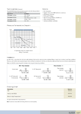
Pressure/Temperature Diagram
P (bar) A
16
15 Metal
14
13
12
11
10
9 PVDF
8 PVC + PP
7 PVDF (PN10)
6
5
4 PVC (PN10)
3
2 50 x DN 5 x DN
1 PP (PN10)
0 T °C
-30 -10 +10 +30 +50 +70 +90 +110
A: Application range for complete device
(fitting + flowmeter) 40 x DN 5 x DN
Installation
50 x DN 5 x DN 25 x DN 5 x DN
EN ISO 5167-1 prescribes the inlet and outlet distances that must be observed when installing fittings in pipe lines to achieve calm flow conditions.
Below you will find the most important layouts that could lead to turbulence in the flow, and the associated prescribed minimum inlet and outlet distances.
Make sure that the measuring point is steady, to ensure good measuring conditions
DN = Pipe diameter 40 x DN 5 x DN Flow direction --> 20 x DN 5 x DN
Pipe diameter
Control valve 2 x 90° elbow joint
expansion
50 x DN 5 x DN 25 x DN 5 x DN 18 x DN 5 x DN
2 x 90° elbow joint 90° elbow joint Pipe diameter
3 dimensional or T-joint reduction
40 x DN 5 x DN 20 x DN 5 x DN 15 x DN 5 x DN
Ordering Chart 25 x DN 5 x DN 18 x DN 5 x DN
Description Item no.
Hall 423 913
Hall (use with 8025) 20 x DN 5 x DN 15 x DN 5 x DN 423 914
Meter for High Temperatures * 449 694
*see separate datasheet 8030, for high temperatures
18 x DN 5 x DN
Note: The electronic module, SE30 and the fitting, S030 must be ordered separately
15 x DN 5 x DN
427