
Page 429 - Bürkert
P. 429
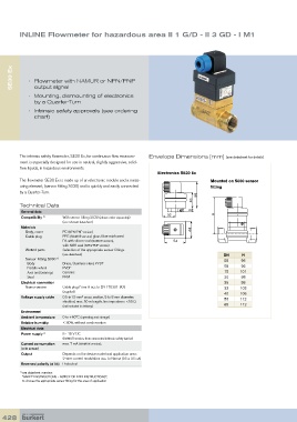
INLINE Flowmeter for hazardous area II 1 G/D - II 3 GD - I M1


      SE30 Ex  •   Flowmeter with NAMUR or NPN/PNP


               output signal
            •   Mounting, dismounting of electronics
               by a Quarter-Turn
            •   Intrinsic safety approvals (see ordering
               chart)


         The intrinsic safety flowmeter, SE30 Ex, for continuous flow measure-  Envelope Dimensions [mm] (see datasheet for details)
         ment is especially designed for use in neutral, slightly aggressive, solid-
         free liquids, in hazardous environments.
                                                                Electronics SE30 Ex
         The flowmeter SE30 Ex is made up of an electronic module and a meas-        Mounted on S030 sensor
         uring element, (sensor fitting S030) and is quickly and easily connected    fitting
         by a Quarter-Turn.
                                                                                66
                                                                              40
         Technical Data
          General data                                                        9        H
          Compatibility  1)  With sensor fitting S030 (please order separately)  32
                          (see relevant datasheet)
          Materials
            Body, cover   PC (NPN/PNP version)                                44
            Cable plug    PPS (NAMUR version) glass fibre reinforced
                          PA with silicon seal (NAMUR version),        54
                          with NBR seal (NPN/PNP version)
            Wetted parts   Selection of the appropriate sensor fittings
                          (see datasheet)                                                  DN     H
             Sensor-Fitting S030                                                           06     96
                        1)
              Body        Brass, Stainless steel, PVDF
            Paddle wheel   PVDF                                                            08     96
            Axis and bearings   Ceramic                                                    15    101
            Seal          FKM                                                              20     98
          Electrical connection                                                            25     98
            Namur version  Cable plug Form A acc to EN 175301-803                          32    102
                          (supplied)                                                       40    106
          Voltage supply cable  0.5 to1.5 mm  cross section, 5 to 8 mm diameter;           50    112
                                  2
                          shielded, max. 50 m length; line impedance <50 Ω
                          (not included in delivery)                                       65    112
          Environment
          Ambient temperature  0 to +60°C (operating and storage)
          Relative humidity  ≤ 80%, without condensation
          Electrical data
          Power supply  1)  8 - 15 V DC
                          (NAMUR version, from connected intrinsic safety barrier)
          Current consumption    max. 7 mA (NAMUR version);
          (with sensor)
          Output          Depends on the device model and application area:
                          2-wire current modulation acc. to Namur (0.5 or 2.5 mA)
          Reversed polarity (of DC) Protected
         1)   see datasheet overview:
          “SAFETY INSTRUCTIONS - NOTICE OF ATEX INSTRUCTIONS”,
          to choose the appropriate sensor fitting for the area of application


  428