
Page 430 - Bürkert
P. 430
Technical Data (continued)
Complete device data (sensor fitting + electronic module)
Pipe diameter
S030 sensor fitting DN06 to DN65
Measuring range
S030 sensor fitting 0.5 to 1200 l/min (velocity 0.3 to 10 m/s)
Medium temperature max. 80°C (176°F)
Fluid pressure max.
S030 sensor fitting PN10 (PVDF), PN16 (stainless steel, brass - PN40 on request) SE30 Ex
Viscosity
S030 sensor fitting 300 cSt. max / 1% max. pollution
Accuracy
S030 + Electronics SE30 Ex
2)
Teach-In (via remote transmitter) ±1% of Reading (at the teach flow rate value)
Standard K-factor ±2.5% of Reading 2)
Linearity ±0.5% of F.S.*
Repeatability
S030 sensor fitting ±0.4% of Reading 2) ** For the 97/23/CE pressure directive, the device can
Standards, directives and approvals only be used under following conditions (dependent on
Protection class IP67 with connector plugged-in and tightened acc. to EN 60529 max. pressure, pipe diameter and fluid).
Standard and directives Type of fluid Conditions
ATEX see ”SAFETY INSTRUCTIONS - NOTICE OF ATEX INSTRUCTIONS” Fluid group 1, §1.3.a DN ≤ 25 only
EMC EN 61000-6-3 Fluid group 2, §1.3.a DN ≤ 32 or 50 x DN 5 x DN
EN 61000-6-2 DN > 32 and PN*DN ≤ 1000
Pressure (with S030 sensor fitting) Complying with article 3 of Chap. 3 from 97/23/CE directive.* Fluid group 1, §1.3.b PN*DN ≤ 2000
NAMUR EN 60947-5-6 Fluid group 2, §1.3.b DN ≤ 200
2) Under reference conditions i.e. measuring fluid = water, ambient and water temperature = 20°C (68°F), applying the
minimum inlet and outlet pipe straights, matched inside pipe dimensions. 40 x DN 5 x DN
* F.S. = Full scale (10 m/s)
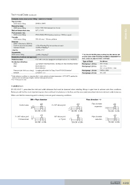
Installation
50 x DN 5 x DN
25 x DN 5 x DN
EN ISO 5167-1 prescribes the inlet and outlet distances that must be observed when installing fittings in pipe lines to achieve calm flow conditions.
Below you will find the most important layouts that could lead to turbulence in the flow, and the associated prescribed minimum inlet and outlet distances.
Make sure that the measuring point is steady, to ensure good measuring conditions
DN = Pipe diameter 40 x DN 5 x DN Flow direction --> 20 x DN 5 x DN
Pipe diameter
Control valve 2 x 90° elbow joint
expansion
50 x DN 5 x DN 25 x DN 5 x DN 18 x DN 5 x DN
2 x 90° elbow joint 90° elbow joint Pipe diameter
3 dimensional or T-joint reduction
40 x DN 5 x DN 20 x DN 5 x DN 15 x DN 5 x DN
25 x DN 5 x DN 18 x DN 5 x DN
20 x DN 5 x DN 15 x DN 5 x DN
18 x DN 5 x DN
15 x DN 5 x DN
429