
Page 424 - Bürkert
P. 424
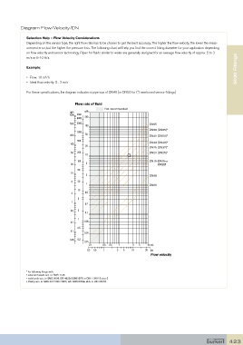
Diagram Flow/Velocity/DN

              Selection Help – Flow Velocity Considerations
              Depending on the sensor type, the right flow rate has to be chosen to get the best accuracy. The higher the flow velocity, the lower the meas-
              urement error, but the higher the pressure loss. The following chart will help you find the correct fitting diameter for your application depending
              on flow velocity and sensor technology. Pipes for fluids similar to water are generally designed for an average flow velocity of approx. 2 to 3
                                                                                                                     S030 Fittings S030 Fittings
              m/s or 6-10 ft/s.
              Example:

              •  Flow: 10 m /h
                       3
              •  Ideal flow velocity: 2... 3 m/s

              For these specifications, the diagram indicates a pipe size of DN40 [or DN50 for (*) mentioned sensor-fittings]

                                      Flow rate of fluid
                                                    Not recommended
                                           3
                                   gpm    m /h
                                   1000  l/min  200
                                       3000
                                   500  2000                              DN65
                                           100
                                                                          DN50 (DN65)*
                                       1000
                                   200     50                             DN40 (DN50)*
                                       500
                                   100                                    DN32 (DN40)*
                                           20
                                                                          DN25 (DN32)*
                                    50  200                               DN20 (DN25)*
                                           10
                                       100                                DN15 (DN15 or
                                    20     5                                   DN20)*
                                       50
                                    10
                                           2                              DN08
                                    5  20
                                           1
                                                                          DN06
                                       10
                                    2      0.5
                                       5
                                    1
                                           0.2
                                    0.5  2
                                           0.1
                                       1
                                    0.2   0.05
                                       0.5
                                    0.1
                                          0.02
                                   0.05  0.2
                                          0.01
                                             0.1   0.3  0.5  1    3  5   10 m/s
                                            0.3  0.5  1   3  5    10    30  fps
                                                                           Flow velocity


              * for following fitings with:
              • external threads acc. to SMS 1145
              • weld ends acc. to SMS 3008, BS 4825/ASME BPE or DIN 11850 Series 2
              • Clamp acc. to SMS 3017/ISO 2852, BS 4825/ASME BPE or DIN 32676


                                                                                                                 423